I'd run 3 x 20amp breakers on the same leg using 10 gauge cable.
15 amp circuit VS. 20 amp Circuit
Hello,
I’m in a situation where my audio room has one ( three outlets ) 15 amp circuit. It appears to me that the 3 outlets in this room are connected in series , meaning drawing current from one outlet will drain the other two .
For 2 channel audio , I have connected my C12000 pre amp, McD12000 and through MPC1500 conditioner and to one of the 15 amp outlets . This should be okay? However, problem could arise once I connect the McIntosh 1.2k power AMPs to the other 2 outlets.
I would like to know if I need any dedicated circuit for my equipment . It appears I need more power than 1400 watts ( 15 amp circuit can provide ) when I use my home theater Where I will have Four 1000 watt woofers and 3 additional AHB2 amps.
Question :
howmany dedicated 15 amp or 20 amp circuits do I need to ensure smooth power without dimming the lights around the house / prevent possible fire ?
Please provide your suggestion based on the below equipment .
DAC: McIntosh MCD12000
Power Conditioner: MPC15000
preamp : McIntosh C12000
AV Processor : Marantz 7015
power AMP: Two McIntosh 1.2k
power AMP: Three AHB2 , one used in MonoBlock
Streamer : One Streamer
70 responses Add your response
I'm assuming you don't run 5 power amps at the same time. In reality, your entire system, when running, probably draws +/- 5 amps. Your 15 amp breaker can handle a constant draw of 12 amps, and shorts bursts above 15 amps without tripping. Yes the lights might dim for a second when you fire the amps up, but that's a momentary rush of current. If running dedicated lines makes you feel good, go ahead. I doubt you will ever notice a difference in sound. IMHO |
I will run all 5 power amp at the same time . And it will be for home theater . the light dimming issue, is happening with every base when I turn up volume . each subwoofer is 1000 amps , so potentially , 4000 watts can be drawn just by the amps . While the 15 amp circuit can provide max 1800 watts. ( I’m better off to use a 20 amp circuit just for subs ) now with 3 bench mark at average 300 watts per amp , that’s about 1000 watts just from the 3 benchmark amps —-> , that can stay on the shared 15 amp circuit the 2 McIntosh 1.2k amp, each can draw 1200 amps ( so definitely a dedicated circuit just for these 2 ) |
When not just put in dedicated 20 amp outlets bigger 10 or 12 awg Copper wiring I used awg 10 using a 4 wire setup my audiophile friend showed me . hot ,neutral , common ground ,and a isolated insulated ground on its own buzz bar and grounding it works great and always quiet not sharing common ground with everything in the house. |
Check the wire on the existing circuit. If you have 12 awg, replace the 15 amp breaker with a 20 amp. If you have 14 awg, do not upgrade the breaker. Remember, many homes have 20 amp breakers but use 15 amp receptacles in series. 10 awg wire is usually rated up to 30 amps. However, if you have a long run, you can use 10 awg for the 20 amp circuit. If you’re running a home run for each receptacle, use 20 amp receptacles. Hubbell makes high quality hospital grade receptacles worth consideration. Hope this helps. |
I'd personally have run 3 dedicated lines in my new listening room, 2 for amps and 1 for signal components; but I am NOT an electrician.....and will only be running one amp at a time. As others have mentioned, used audiophile receptacles. There are lots of good choices, but I can recommend: Furutech GTX-D (G - Gold), Furutech GTX-D (R - Rhodium), Oyaide R-1 (NOT the SWX series), and for cost conscious Acme Audio Labs Silver cryogenic with CFC coating (Revolution Audio). Check around on pricing, the Furutechs and Oyaide R-1.....prices can vary by about 30% depending on where you buy them. |
Most responses are correct. The most important factor is to dedicate the power supply run to your audio console; i.e., run a 12/2 cable (with ground) directly from your power entry panel in your home/apt. to a dedicated outlet for your audio gear. Using that outlet to then feed a surge protected and individually filtered multi outlet strip to feed each component. This will be a "quiet" feed with no influence on that direct circuit, and also reduces/eliminates ground loops within your system. Of course there will be some voltage drops/spikes/noise at the AC panel from refer's, blowers, AC, etc. but that will be somewhat attenuated by the filtering of the strip. If you really want to get into high performance, low noise power distribution there are books describing how to set up home/commercial recording studios, specifically dealing with power distribution. BTW, standard OTS electrical components and wire are fine. Save your money for your audio gear.
FYI am an electrical engineer by trade, mostly designing power distribution for mobile and marine applications, but many of the principles' remain constant for home/commercial applications. |
The old-fashioned way would be to look up how much amperage is used for each component and then add up the total. The specs should be in the owner’s manual and/or the back plate. The amperage will increase for the amps during playback - so select the maximum draw as per the owner’s manual. - - - Watts = Amperage x Voltage. This formula will help figure out the amperage if it’s not listed. How’s your algebra? - - - - Ideally, from an electrical perspective, the same amount of amperage should be on each separate circuit - to keep the legs (phases) balanced. It’s highly unlikely that anybody actually does this in their home - and it’s not dangerous with a good utility panel installed. Balanced phases are used primarily in industrial/commercial installations. (Balanced phases vs Balanced power are two completely different applications.) - Ideally, from an audio perspective, the digital components should be on a separate circuit than the analog components. Or they can be separated via a power conditioner if a circuit is to be shared. - - - -
It doesn’t work that way. Neither the current (amperage) - nor the voltage - will be affected as long as the load is under the circuit rating. If the load is over the rating, the voltage may reduce and the wire itself will get warm to hot - depending on the load. The circuit breaker should trip if the load the load is too high - thus preventing any electrical fires. - - - |
Tempest in a tea cup. The power draw (E x I) from an average home audio system is negligible, unless you're running quad Class A mono blocks at 100 wpc each to supplement your home heating system. Even 200/300 wpc class AB amps average less than 5 amps , and 15 amp circuits will handle this even added to preamp, DAC, PC, Streamer, Turntable, etc. It's clean power you're after, and no noise (ground) loops. Also, well designed audio gear will have power supplies that are deigned to operate in real world conditions, so again spending a fortune on cables/outlets, magic fuses is a waste of capital. |
@impaler you do not think this could be a fire hazard as I will be potentially pulling 4000 watts from subs , 2400 watts on AMP 1 and 2 and 1000 from other amps ? A 15 amp outlet can only cover up to 1800 watts max . How is it okay to draw 5000+ watts from 3 outlets that are interconnected to one 15 amp breaker ? |
@joshziggie2021 Don't lisen to @impaler he doesn't know what he is talking about, you will get better performance from your equipment with dedicated 20 amp circuits. The problem with people who use math on this type of problem is they don't realize just how much the current draw is for really short durations, you can't measure it with a multimeter. |
invalid Sorry to agree to disagree. What you are referring to is the instantaneous peak load response and what you would call droop in that particular measurement, measured in microseconds. To some extent effected by wire gauge and contact resistance in the power delivery circuit, source impedance etc. My point was you would need a great deal of that differential to notice a 15 or 20 amp circuit difference. This can be verifiable if you want to take it to that level. Sometimes sound science and engineering are good things so people aren't wasting their money on snake oil. Again no disrespect to your opinion. joshziggie2021 In your particular case, I am indeed puzzled by the specs you are stating. 4kW for subs and 3.4kW from other amps? This represents a truly incredible amount of energy and, in your case if you are experiencing anywhere near these load values, that would best be served by a minimum of a 60 amp circuit at 120VAC, (30 @ 220VAC)Running 6 or 8 AWG cable. Those load values would be similar to a sound reinforcement system for a small stage. Please guys, I do this for a living. I'm very much all about a solid power supply system, but science and math should dictate, not guesswork. |
I feel we often confuse the Watts rating of our equipment with the real world power they use. I have two Hegel H30 mono amps rated at 1150 watts each. In theory, I require 19 amps just for these. I can tell you that they only draw about 5 amps combined when I am running them. With all the equipment the OP is using, I can see the need for more than one 15 amp breaker. I could be wrong but I would bet the sub amps are D Class and don't draw anywhere near 8 amps (1000/120). Your dimming lights suggest another breaker is required but the fact you're not constantly tripping the current 15 amp breaker tells the tale. |
bigtwin Exactly correct, wattage rating for a particular appliance is a UL/CE requirement based on very specific tests and results. As I mentioned, those power levels (continuous) are unheard of in home audio. The dimming lights is another issue altogether, and the breaker size isn't going to help that. This is a source power issue, and could be poor connections in the primary feed, under-rated house/apt current supply, generally lower than normal voltage at source, or even an under rated/over utilized transformer at the pole. You have to id the problem before you can fix it. |
| Post removed |
Some good comments above from some quite knowledgeable folks - nice to see and is why I like to frequent this forum. I agree that adding a couple of dedicated 20A circuits with 10-12 AWG wire should do it _ IF the in-wall wiring back to the breaker is the problem. The only unaddressed point (as of when I started typing) came in the OP's second post where he specifically comments on the lights dimming. (…the light dimming issue, IS happening…) More info on how this manifests itself might help us help the OP. If lights dim, something is not up to snuff somewhere. Are they in the same room and on the same circuit? If so, then that narrows things down a lot. If dimming happens elsewhere in the house and NOT on the same circuit, then I would IMMEDIATELY ask an electrician or the utility company to check the service entrance feed to the building. Some utilities won't check past the meter so you may need the electrician for a "last mile" check between the meter and your breaker box. A non-direct analogy - I once moved into a building and found one leg that fed my stove was leaning against its connecting lug - not clamped at all. Truly scary. Not every installer is working at 100% all the time. There may be a loose connection at one of your outlets or anywhere back to the breaker box or even the pad mount or pole. Terminology / grammar check: You have a SERIES of outlets connected in PARALLEL along the circuit, so each gets the full voltage. At some point back-wiring came into vogue to speed installation. That enabled installers to just poke the wires into holes in the back of the receptacle. No loops around screws that need to get tightened just right. Fast and easy, but not nearly as good a connection and then the receptacle essentially becomes a buss bar and IS in series with the other outlets, but each plug-in point is still in parallel with all the others. Another take on the series / parallel issue: A good wiring job with large wall boxes and lots of space will have the wires going to the breaker box come to a 3-way connection, with the lead to the next box under the wire nut as well as a short pigtail to the receptacle in the box. This way the receptacle is never in Series with the other devices down the line and the inevitable movement from thermal expansion and years of plugging and unplugging devices has less impact on the connection at each device, and half as many connection points to loosen over time or be suboptimal initially. 15A breaker and 15A outlet circuit? Some guys may have cut a corner and only used 14 AWG light fixture wire instead of the 12 recomm for outlets, esp since the push-in receptacle back wiring connection holes are not supposed to accept 12 gauge and it is so much quicker, easier and cheaper to just cram the smaller 14 AWG in a hole. You can also get a lot more voltage droop that way. Back to the HT room. How / when does the light flicker manifest itself? During a major but quick explosion, an extended pass of a tank rumbling past you, Aircraft takeoff or extended pipe organ bass note? A long rumble will deplete much of the stored power in most amp power supply capacitors. Transients are easy, but extended high ampere power response sucks once the caps go flat. If things blink on even a loud, but SHORT rumble, then maybe a PSU capacitor is no longer up to snuff. Seek it out. Lots of how-to info elsewhere. I would rotate through my amps and see if I can narrow down my search first. If basic fixtures and wiring were both up to snuff, then the lights should not follow the music. Upgrading to Audiophile outlets, in-room cables, etc. can be done later if you want as frosting on your cake! |
That’s a lot of gear. Honestly if you weren’t going to run them at maximum output all the time you are probably fine so long as you don’t try to turn them all on at once. The better your wiring to your stereo, the more likely you are to dim the house lights. :) What you should be concerned with is more current on 1 circuit = more voltage drop, and of course, eventually tripping a breaker. I’d consider running a 60 A sub panel to your room, and from that panel run 2 or 4 dedicated 20 amp circuits. The big advantage is the 6 gauge wiring will result in lower voltage drop overall. Worth considering an in-panel surge protector as well for your gear, both in the main and in the subpanel. It’s not as good as a series mode device (Furman or ZeroSurge) but better than not having them. |
@mickeyb thanks! Yes I have some one installing 4 dedicated 20 amp circuits . |
First, a dedicated circuit is always preferable. Second, no, your loads are absolutely not connected in series. Loads are connected across the hot and neutral, in parallel. Third, yeah, probably 3 dedicated circuits, all pulled from the same leg (same side of the breaker box) to minimize potential ground loops and different ground impedances. |
AI says : Connecting two 20 amp circuits to the same leg of a power source is not recommended as it can overload that single leg, potentially causing issues like uneven power distribution, tripped breakers, and potential damage to your electrical system; it's best to spread the load across both legs of the power supply by connecting circuits to different legs whenever possible |
@joshziggie2021 what you looked up is correct, but some people would say you could get a ground loop from two different legs, though I have never had this happen. There definitely is voltage drop with a 15 amp circuit, stereophile measures it all the time when measuring high powered amps. |
The outlets are not wired in "series" they are wired in "parallel"; series wiring is the old Christmas light string that goes dark when any bulb fails.. Let us assume you have 120 Volt available, and that the breaker and outlets are in good condition, you would need a load of 1,800 watts to reach the breaker's tripping point. These are rough off the top of my head calculations, AC is weird when it comes to Ohm's Law. 1.800 watts would be a very brightly lit room if illuminated by 100 watt bulbs at circuit capacity. The purposed of a circuit breaker is protection, both load, or appliance, and the distribution system, or wiring. By protecting these two aspects, the structure is protected. If you are tripping your 15 amp- Circuit Breaker it might be that the breaker has aged (and they do age), connections have loosened (like with aluminum wire instead of copper), or maybe some corrosion has occurred at the connections. I would not arbitrarily increase the amperage of a circuit breaker. The danger would be removing the "fuse" function from the breaker, and actually making the wiring the default "fuse", which can produce dire results. When your house was built the maximum electric loads would have been a table lamp, a clock radio, a vacuum cleaner, maybe a TV. Fortunately there are some easy and inexpensive solutions to this perceived problem. First replace the old, probably aged and poorly preforming Circuit Breaker with a new quality unit that is compatible with the panel. Then replace the outlets with quality units. I wouldn't worry about an orange or red outlet as much as I would be concerned with dissimilar metals at the connections. And, for goodness-sake use the screw terminals not the stab in connections on the outlets. At this point spending money on expensive AC cables (even if said cables are tre chic) could be better spent on the record collection. If you have the disposable income to rewire and replace the service entrance and panel for the house, or just one room,.. good for you. This is NOT a DIY job, and you should have an engineer or Master Electrician involved, be clear about what you want, and obtain the proper permits. The National Electrical Code (NEC) is all about FIRE PREVENTION, really, no kidding. |
| Post removed |
@jea48 That's the best advice I have read on this thread. |
@joshziggie2021 AI also says if a shirt takes 3 hours to dry in the sun and pants take 4 hours, then 2 shirts and 2 pair of pants will take 14 hours to dry If you have a 200 Amp service in your house, each leg has a capacity of 100 Amps. as long as you don't overload that leg by wiring it for more than 100 amps total, you have no issues. If you have a 400 Amp service, same story, only 200 Amps per leg. if you do as the AI says, you stand a much larger chance of having a voltage differential between neutrals with resulting hum and noise issues. Conventional home wiring was never intended for applications that shared neutrals or grounds across different bus legs. An AI only knows what it has been taught from it's model. AIs are incapable at this point of creating an original thought, like when to use a parallel process vs. serial process when solving our solar dryer question. Or inferring that minute voltage differentials when loads have different neutrals or grounds will create a differential noise level in a complex audio system. |
| Post removed |
| Post removed |
This has been a great conversation, and an excellent read. What I know (in my system): Installing dedicated lines for my power amps and signal components made very noticeable SQ improvements. Adding audiophile receptacles added more improvement. Adding well made, high quality power cables with high purity copper added more improvement. In total the improvements were certainly the equivalent of a component upgrade......or just marginally less. Thanks to all who added to this conversation |
| Post removed |
Good morning, the music output "Watts" is not equivalent to the actual electrical Watts demanded from the AC outlet. Typically, the manufacturer's label on the device gives the actual load in Amps or Watts and even that has a factor of safety you are not likely to see. If the music watts were real, every common household with a home theater would be tripping breakers all the time - and long before anything catches fire by design. Take care! |
@speelerr tripping the breaker is a separate issue, an amplifier can draw huge amounts of current for very short durations, which will not tripp the breaker, but it will cause a voltage drop. |
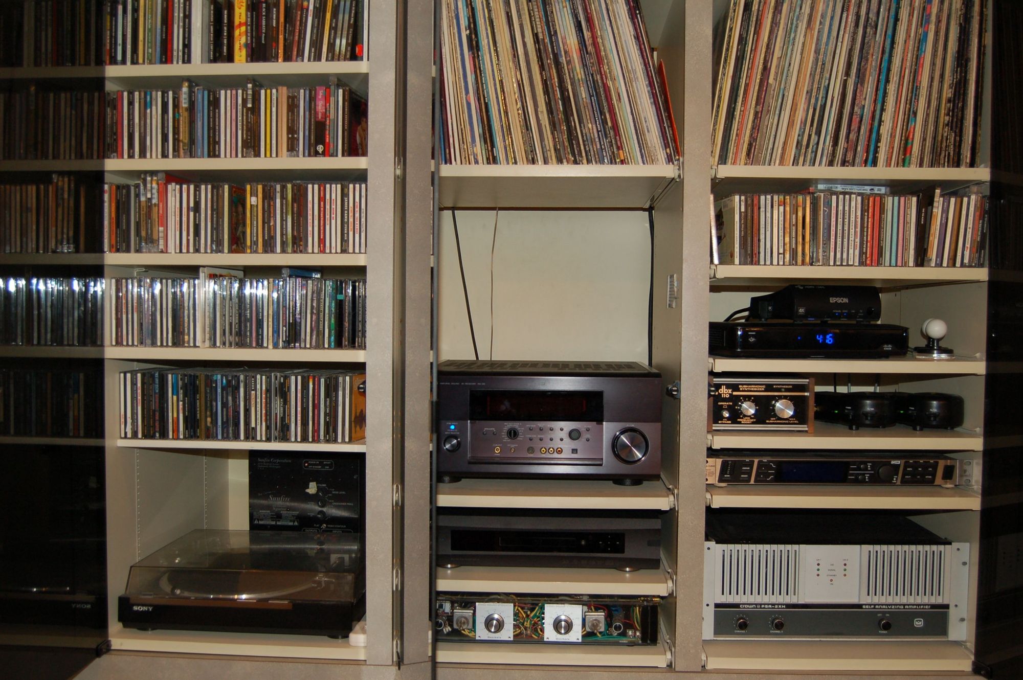
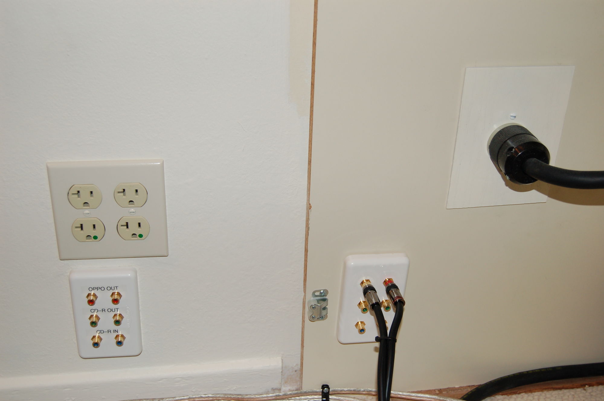
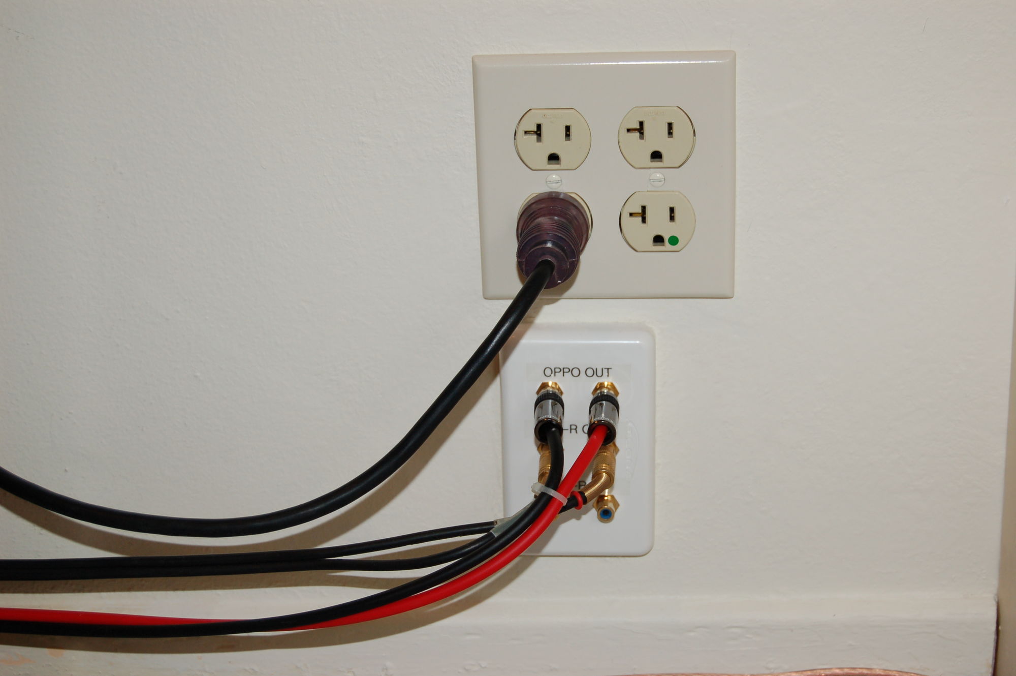
I rewired my home entertainment system when I saw a good deal on a 125’ spool of 8 gauge wire. There are NO splices along the line and it terminates in a 30 amp plug that feeds the industrial surge protector for equipment in the entertainment center and two hospital grade outlets just outside the center. (Again, all a continuous run without splices.) The "power consumers" in the center include a Yamaha RX-Z9 Receiver (1,200 watts rated input), a Crown PSA-2XH (eXtended Headroom), bridged, making about 800 watts into a 12 ohm load (20 amp rated input), and a Sunfire Signature sub (2,500 watt disclamer) The line got it’s own 20 amp breaker, and I even put a big ferrite bead on the line. The Yamaha SACD became less grainy, but I didn’t really notice any audible difference in the Oppo95, which uses a better power supply.
|
@invalid , the “large” short burst of current is feed by the capacitors. Most amps have an AC line fuse of less than 15amps, therefore, the fuse will blow before the breaker (assuming a 15 amp breaker) |