I did some research and couldn’t find a definite answer. I have an amp that I tried 6 different pairs of 5U4G and 5U4GB. 3 pairs has arcing (RCA 5U4G, TungSol, Svetlana 5C3S) and 3 pairs don’t (RCA 5U4G with hanging filament, EH 5U4GB, Sylvania 5931). I took the amp to a technician and he checked everything, he can’t find anything wrong. The problem is, I like the sound of the TungSol and Svetlana which both have arcing. The technician said it is ok to keep using them, but honestly I am not too comfortable. But I like their sound. Is it really ok to keep using the arcing tubes? Will it damage the amp?
The 5U4, being a directly heated rectifier, is a far simpler tube than a KT88 or like; I really doubt the ones you had were bad. These tubes are generally pretty reliable because they are so simple! Keep in mind that tubes, especially older NOS tubes, can be quite forgiving when their specs are exceeded as long as those specs are not exceeded for too long.
Because this is a directly heated rectifier, one way the tube can fail due to arcing is the filament can open up- causing the tube to simply die with no (apparent) fireworks. This is because its two cathodes serving the two plates are in series.
Given your prior experience thus far I expect if you didn't make the changes in the power supply previously suggested that you'll be seeing this problem again.
You mentioned one of your 5931 dies after adding diodes that lead me to restudy the schematics and found that the peak inverse voltage(PIV) of a single 1N4007/UF4007 is not high enough for the job. If in the future you decide to retry the diode mods please use two 1N4007/UF4007 in series to double the PIV or use a diode with higher PIV rating.
Just want to provide an update. I tried adding the diodes but then one of the Sylvania 5931 (which is a rugged 5U4G) dies. I had one of these died died before adding the diodes. And they didn’t arch, but just died with no sound. I think it is not conclusive if the diodes works or not because the tube and symptom are different. But I am concerned and took out the diodes.
then I bought 3 pairs of 5U4GB, 2 pairs of TungSol and 1 pair of Westinghouse. So far so good. I will keep observing. Maybe the amps are just more demanding on the tubes, and some of the old tubes I tried are just bad.
i would say I like them. I sold my X5 before I bought this amp. I am using them to drive a pair of JBL 4341 now. I only have 3 power amps to compare: a custom built 300B by Otomon Lab from Japan using Luxman mq-300 schematics, the ANK, and Coincident 211 Dragon. I then sold the Otomon Lab. The ANK sound as good as the Coincident yet different. The ANK are faster, a bit lighter, better mid range, and a bit more holographic. The Coincident also sound very good. It is a 211 push-pull delivering 75W per channel. It produce a lot more power but also sound very lively and holographic. I had a McIntosh MC 275 IV before. It is a KT-77 push-pull, and it sounds boring and flat, which leave me an impression that is the characteristic of a push-pull amp. It is not the case for the Coincident. On my Harbeth 40.1, it will be clear it needs the Coincident 211. But for my JBL, both sounds great.
it is a Audio Note Kit, not the Audio Note UK. However, there is a bit of a history. What I learn is that the circuit of this monoblocks is initially designed by Andy Grove who is a prime engineer at Audio Note UK.
I'm surprised Audio Note would market these amps with what seems to be a design flaw. Are others experiencing same issue, and if not, I'd think it could be improper assembly.
@gte357s- besides the arcing problem, are you enjoying your ANK monoblocks? Are these driving your Spatial X5s? Are yours the parallel SET amps? What 300Bs are you using?
I'm also using mine to drive OB speakers - GR Research NX-Oticas - which also have powered woofers. Mine aren't as efficient as the X5s though, at 92.5db. But I'm going to replace the NX-Oticas with GR Line Force speakers (hopefully) in the next few months - just waiting for the cabinets to be completed and I can start assembling them. The Line Forces are 99db/w efficient so the 300B amps should have plenty of power.
btw - it's only the interstage and output transformers that are C-core. The mains transformer and choke are more conventional (EI-core I believe).
I first commented on the start/inrush as well as pointed out a source (though I did not know how to forward/link it) to a schematic of the power supply.
That’s my amp on the Steve Hoffman forum. I haven’t had any issues with arcing but as you can see in my thread, I used a soft start before the mains transformer, and also have a lot less capacitance hanging on the output since I used a Maida regulator for the driver tube.
atmasphere - Thanks for taking the time to educate, me anyway. I have always appreciated and respect the knowledge you and imhififan have brought to the AG forum.👍
You work out the timing constants. The amp likely does not have a timing constant in the audio circuit that is less than 5Hz since the output transformer won't go down anywhere near that. So it will not be able to modulate the power supply if the power supply has timing constants of below 5Hz. 220uF is way overkill; I don't know of a tube rectifier that will survive that.
Not only that and more importantly, the load on the power supply is constant owing to the circuit is class A- it draws the same power at idle as it does at full power. This makes the power supply requirements a lot simpler. That is why 47uf will be fine. I have an amp that makes the same power and it has only 30uF in this position. The power supply voltage dominates the equation when you're talking about energy storage to do work (like driving a loudspeaker). The formula is:
Work = 1/2 (C x Vsquared)
That is why tube amps don't need nearly the power supply capacitance as solid state amps do.
A few years back I built an ANK Kit-1 300b stereo power amp.
The rectifier tube arked upon power up. I contacted ANK’s builder at the time and he suggest trying a new EH 5u4gb. Told me to buy two or three cause one might ark even new, so throw it away (and any other rectifier tube that arks at startup).
I bought three and only one arked at startup. I marked it and some others but never threw them away lol.
It’s been working fine ever since although I don’t use it constantly.
I did notice shortly after that ANK started including the EH 5u4gb with their kits. But that was then.
decay - Are you offended? Your multiple comments here were of no value. I was not commenting on you, as I do see that you do make valid contributions occasionally. My comments were meant to encourage imhififan and atmasphere to contribute more often. I have a lot of respect for both of them.
My 2cents - Seems clear that this an inrush current problem, which reducing the capacitor values would help to reduce. It has been my experience that reducing power supply capacitance does usually negatively affect low frequency capabilities. If I were going to reduce the cap values, I would not reduce more than necessary. Say from 220uf to 100 instead of going all the way down to 47uf. The diode idea was excellent. How about doing both, diodes and just the 220uf caps to start with?
@atmasphere Thanks for the info. I think so will experiment the diodes approach first, because it is cheap and easy enough to do it myself. It is also a good learning experience for me. At the same time, investigate on changing the capacitors. It seems it is not too difficult to do as well, if the size are the same.
There won't be another tube rectifier that will work better. The problem is that this circuit is designed to expect the voltage drop that exists with the 5U4 at the current at which its operating.
I gave you a range of capacitor values. But to be clear:
replace the 220uF units with 47uF. Replace the 100uF units with 22uF.
Once this is done you'll find additional diodes to be moot. They may also cause commutation noise by interacting with the inductance of the power transformer winding, which can manifest as an annoying low level buzz. If it were me I wouldn't bother and instead work on correcting the problem.
Just like seat belt and air bags, more protection is better, IMO.
However, some might think that put a silicon diode in a tube power supply is a sin! If that’s the case, you can install soft start alone.
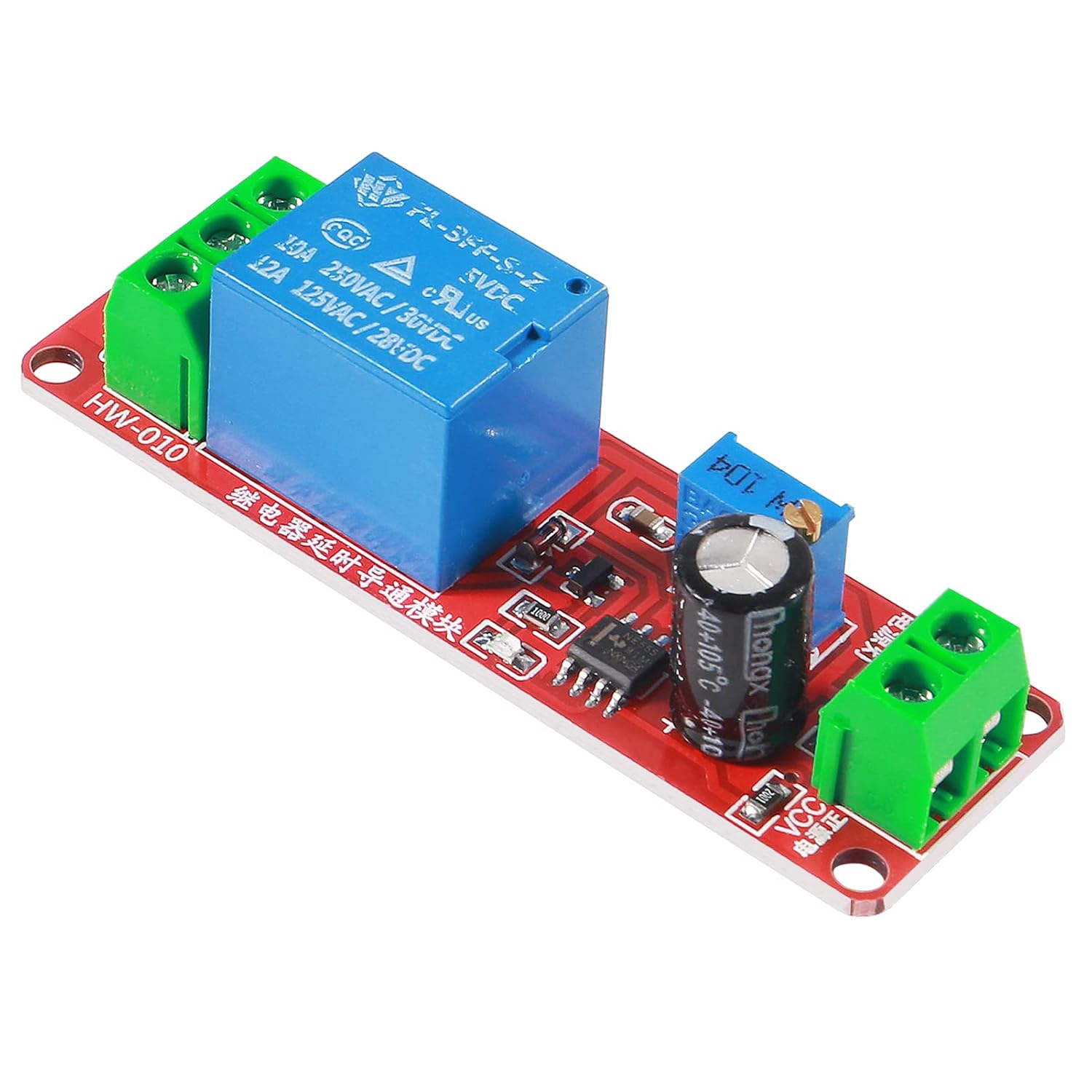
The soft start device is a CL-70 NTC thermistor in series between the fuse and the "hot" wire to power transformer primary winding. 10 seconds after power up, a time delay relay which connect to the power transformer 5V winding will turn on and bypass the thermistor. Both items are available on Amazon.com
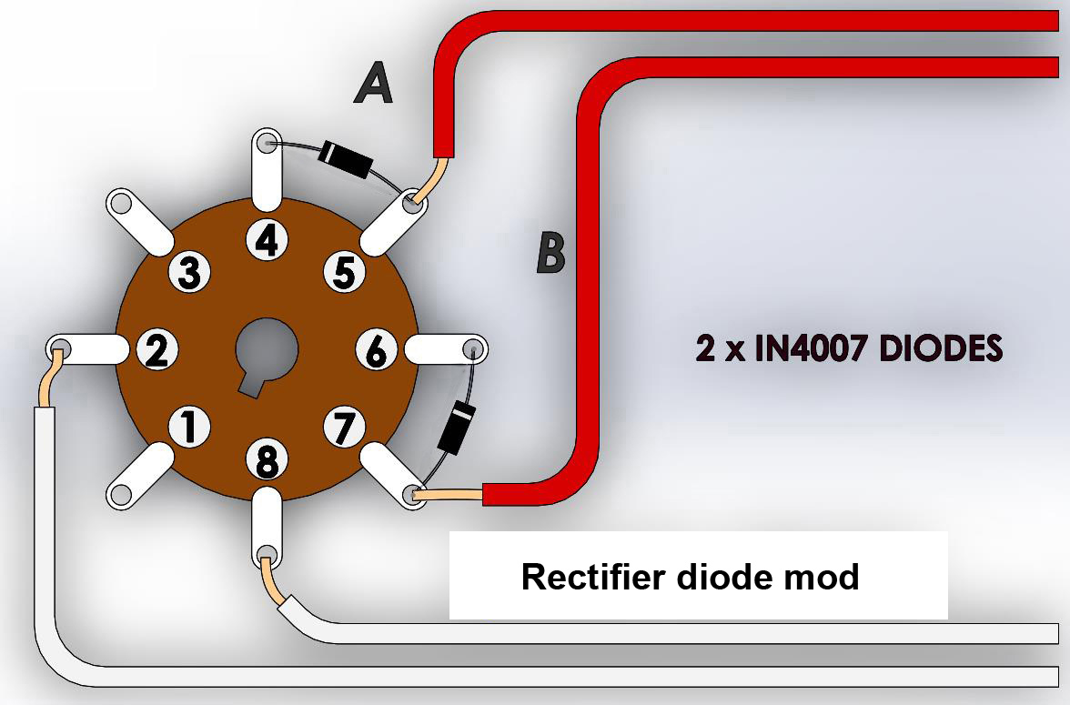
Yes, I found a picture on the web that show the details
You can solder the diodes on the socket and move the wires accordingly. you can use 1N4007 diode, but UF4007 is better (lower noise) and just cost a few cents more.
BTW, if you interested add on a NTC soft start device please let me know, it just cost less than $20 in parts. Since it will be bypassed in 10 second after power up, it will not affect sound quality.
also to make sure, the diodes should be added at pin 4 and 6 as shown in the second diagram above, with the line on the diode closer to the pin, am I correct?
"Finally, some real help for this problem. Thanks for helping to solve problems that the wannabees simply cannot."
You have contributed nothing useful to this thread (instead you have performed as a cheerleader with your +/- opinion of those who have contributed useful info/avenues of thought).
IMO, reduce the capacitor value will has a bigger impact in sound quality, those 220uF capacitors are mounted into a 35mm clamp with point to point soldering. You need to find a 50uF cap with similar quality and diameter to fit into those clamps or you need to find a way to mount them into the chassis if the caps has different dimension. And the modification cannot be easily reverted!
OTH, install two UF4007 on the rectifier tube socket is a very simple job ( it takes less than 10 minutes ) and those diodes only cost a few dollars. Its also very easy to reverted.
Those diodes are functioned as a protection device to reduce the chances of rectifier tube arcing and also can prolong the life of those rectifier tube. BTW, the effect in sound is negligible.
My suggestion is go ahead install the diodes first, put in some new rectifier tube and see if it solve the arcing problem. If you don’t like the result, then go for the capacitor mods or install soft start device.
BTW, always wait as least 5 minutes to let the tubes cool down before you switch the amplifiers on again as @dekay suggested.
Yes, mine also has 220uF capacitor, and yes, the arcing only happens when the amp is turn on. After than, and if the fuse doesn’t blow, the amps sound fine.
Nailed it!
I would replace the capacitors after the choke with 50uF devices rather than the 220uf units. If anything you might hear a slight improvement since the smaller cap might perform better at high frequencies, if you install ones of similar quality. If you do this there may be no need to install the solid state rectifiers, although the caps in succeeding legs of the power supply are gross overkill (contributing to rectifier failure) as well. You could run 1/5th the value and be fine.
Yes, mine also has 220uF capacitor, and yes, the arcing only happens when the amp is turn on. After than, and if the fuse doesn’t blow, the amps sound fine.
here is the wiring diagram of the capacitor and resistors.
Besides adding diodes, is there other recommended options about changing capacitors or resistors? But I guess changing capacitors and resistors will have a bigger impact to the sound, right?
+1 atmashpere too. I'm not a tube guy, but atmasphere has a point about the caps being too large. I ran into this problem while servicing a Sony V-fet amp. Both of you guys know your stuff.
If it is, that 220uF value seems really high to me! An SET is a class A device so the load on the power supply is constant. If you cut all those values in half I think you’ll find that the rectifiers hold up just fine.
This appears to me to be a classic case of too much filtering (the filter caps need to have a time constant lower than that of the amp and in an SET that isn’t hard...)- when the amp is off, the voltages in the power supply are drained off. When you turn the amp on, as the rectifier warms up current flows to charge the caps. There is a certain point on the exponential charging curve (this is the charging curve of any capacitor) where the maximum current of the 5U4 is exceeded. In due time the tube, which is otherwise pretty forgiving, arcs. If I am right about this the arcing happens as the amp is warming up.
min the diagram, I need to add two diodes per tube, am I correct?
Yes.
I agree something is up in the amps- the 5U4 should easily handle the load all on its own. It sounds like something is causing an excessive load during warmup, which is a classic symptom of the filter capacitance at the output of the rectifier being too large. Both doing the same thing is not coincidence! What is the capacitor value at the output of the rectifier tube? There is no schematic in the manual...
Soft start will help, you also can add an UF4007 to the plate of rectifier tube to removes negative half cycle voltage and it halves the total time of voltage that feeding the arc.
Some/most of it is beyond my tech knowledge as well, but I do understand the basics of it.
I've relied upon techs/friends to update my tube gear in the past and I gleaned a tiny bit of understanding from doing so
This would be good info for your local repair person to read/consider.
Until 10 years ago I did not know what the tiny transformers a friend installed on my Dynaco ST70's, being used as mono blocks, were for (power supply chokes).
He performed the modifications in 1979, and said that the stock mono/stereo switch/circuit was a bad joke.
The improvement in sound quality from the mod was not a slight one.
I have been running tube gear.. at first a couple components… more and more… now all tube. I have never had a piece of equipment that arched. If the second tube arched I would get rid of it. Maybe this Is just me, I have about 50 tubes in the two systems I use constantly, and no arching… never.
I found that thread at the Steve Hoffman Forum. Honestly, what being explained there is beyond my technical knowledge. I like the idea about adding a soft start, but I need to take it to my tech to do that. But do you think adding a soft start will eliminate the arcing?
From what I gathered surfing the WWW 5U4G is the only rectifier recommended for your amps in stock form.
I've only come across them with guitar amps of which a few local guys preferred the 5U4G (over the GB version).
This is of course apples to oranges as far as your AN's go.
Try and find the thread (threads) @ the Steve Hoffman Forums pertaining to your specific amps as there were gobs of posts/pics/info that I did not read through in detail (including power supply/slow start mods).
As they are kits I doubt that well thought out modifications would decrease their resale value down the road.
From the few pics I viewed they looked easy to work on (unlike my old Audion 300B amp that resembled the innards of my TV7 tube tester;-).
I would start by confirming that your units are actually built to the original AN specifications and then go from there.
Yes, it's possible that your old production tubes are duds as I've always found rectifier tubes difficult to test with my old TV7/Hickok 539 testers in that they always tested good until they didn't (same thing with 12ax7 tubes on the same testers).
Short answer is Yes, the arcing happens in both channel.
for the 5C3S, at the beginning, I don’t think they arc. Then after a month, both tubes arc. For the RCA, they both arc right the way. For the TungSol, so far, only one arc. And when I switch the tube, same behaviour.
maybe as you say I have bad luck, but the percentage seems too high, 50% or 3 out of 6 pairs arc. That’s why I think could it be a me doing something wrong which cause this. But there is only one button, I can’t think of anything except I didn’t wait long enough when restarting the amp.
is it very common for 5U4G to arc? I only have two amps that use 5U4G, and I didn’t roll the tube in my previous amp.
If this is "only" happening when you power down one of the amps and then restart it within a very short period of time, just wait longer (5-10 minutes).
If it happening @ other times, then it needs to be looked into.
I would not reuse a rectifier that I observed arcing, but I've always had plenty of spares.
I found a schematic of the power supply section @ the Steve Hoffman Forums, but could not link it.
I Googled your amp + rectifier and it came up on the first page of hits.
A 5U4 should handle that load just fine. I think you've had bad luck with tubes... Is this happening in both channels? Do both channels sound the same?
It is a Audio Note Kit Interstage 300B monoblock. Here is the assembling instructions menu. I have it built by someone and have another technician to go through it, so, I believe it is not a built issue. It is design for 5U4G. However, the company sells the kit, and doesn’t have much detail about the design. Also, they make their own C-Core transformer. I read that one possible reason is the transformer is “too good” and has a much lower resistance than others? Anyway, I think this is more a compatibility issue.
Any suggestion is appreciated, like adding resistor or capacitor somewhere.
You must have a verified phone number and physical address in order to post in the Audiogon Forums. Please return to Audiogon.com and complete this step. If you have any questions please contact Support.