Some vinyl users use a SUT to enhance the signal of the MC cartridge so that it can be used in the MM input of a phono stage. Although I don't understand the theory behind it, I realize that a SUT should be matched individually to a particular cartridge, depending on the internal impedance of the MC, among other things.
Assuming an appropriately / ideally matched SUT and MC, What are the inherent advantages or disadvantages of inserting a SUT after the MC in the audio chain? Does the SUT theoretically enhance or degrade the sound quality? What does the SUT actually do to the sound quality?
I have an experience of listening to a minimum of approx' 10 SUT's in my own system and have been demonstrated somewhere near this quantity again in other systems.
Along with the above, I have listened to, in my own system, a Head Amp, Amps with a built in MC Stage, as both Valve Hybrid and SS.
It is the extended usage in the home system of configurations for devices, that really helps with understanding the impact of a device and enable a reasonable evaluation on the influence during comparisons.
My most recent experiences of encountering New Devices that have left a very good impression are only a few months past.
Outside of my system, I have listened to too many to count Phonostage configurations, using Phono Pre- Amp > SUT or Head Amp, Valve Hybrid MC and SS with the most expensive dedicated design having a £10K price.
I have spent numerous years learning about how the designs and configurations for a Dedicated Phono Amplification can impact on the presentation on offer from a Vinyl LP Source.
I am not prejudiced; I have heard very good performances from a SUT in use, or a Head Amp in use. A SUT does inject a Colour to the presentation, but there are SUT's that in comparison to another could be described as having a Transparency.
Put a perceived as Transparent SUT in use alongside a Head Amp as a comparison demonstration and the SUT will quite quickly have a detectable colour in the presentation.
I see the SUT > Head Amp in use, as real bonus to the user who does not prejudice against the devices, as there is a huge scope to fine tune a system to one's unique preference, the cut off point for detectable colouration is the end users choice. This is achievable, in all Phono Amp Designs, Valve Input/Output, Valve Hybrid and Solid State.
I have pursued the perception of Transparency for a long time, and as a result, have found it difficult to accept an undeniably transparent presentation as attractive. With this in mind, my investigations have shown it is hard to discover SS designs that really appeal, (there are a few that I have appraised with a positive evaluation, as a Brand Soulution is presenting in a way that is very agreeable.)
As a means to achieve the perception that a presentation is attractive, for my own preference, a little detectable colouration is welcome, even though easily able to be overlooked, is the presentation that is very attractive for me. As always each to their own, based on the influences made as a result of their own experiences.
Most recently I was demonstrated SUT's with a design that uses a material referred to as a Nano Crystaline Core. Two different ratios were in use and a Copper and Silver Wire was in use as well. I was shocked (definitely not expecting ) how the devices were able to impress, these are top of the list for a home demonstration, alongside a Solid-State Phon' I have been impressed with, when my system is once more assembled.
At the same demonstration one of the SUT's with a Ratio to perfectly match the Cart' in use was to be used in conjunction with a Brand-New SS Phonostage with a value of £4000, that was a loaned device being demonstrated. The SS Phon's MC Stage was attractive for a New Device, with an allowance being given for further settlement through usage, there was without doubt, potential projected for the device.
With the SUT being used in place of the SS Phon's MC Stage, the impression made was notable, it was a much improved presentation, and all attendees listening were in agreement, even the SS Phon's owner.
The most difficult Phon' design, I have struggled to reconcile with is a common design, from an affordable range, from both Brands and a DIY approach, where using a circuit that is Valve Hybrid with a JFET for the MC Stage, usually if bought through a Brand comes with a pricing from £1500 - £3000. There seems through the consistency of the Sonic I am able to detect, to be an indicator typical parts are used for the circuit. In my evaluation there has been seemingly identical presentations, and not the most attractive of ones heard, that appeal to my preferences.
My experiences pretty much break down into the evaluation, that there are options on the configurations to produce a Phonostage. A Phonostage does not necessarily need to be a one box affair only, using off board ancillaries are totally worthwhile trying out.
An end user can be quite creative in how they are able to produce a presentation that has a very positive impression on them.
Add to the permutations, the trying out of different umbilical's and with Valve Designs the option to try out alternative Valves and the opportunities for creativity really 'gets it freak on'.
Why limit oneself, when numerous options are available without the need to be adorned with any great skills to put them in place.
I had a chance to listen to EM/IA SUT in my stereo yesterday. It was a 1:10 Cu version made for my friends combination of a Lyra Atlas and Marantz 7C preamp. Cable was a .6 meter Nordost Quatrofil. On my turntable yesterday was a SoundSmith Hyperion MKII/Kuzma4p9 going into my Pass Labs XP-27 phono pre. I usually have the pre set on high gain and 500Ohm resistance. So for the SUT, I switched to low gain and 47k resistance.
This experience supports a lot of what has been discussed on this thread. The addition of the SUT made things sound a touch more crystalline and at the same time a touch more dynamic. Bass definition and soundstage depth suffered just a little as did overall transparency. Clearly this SUT works better for the tube MM stage that my friend uses. Not that it sounded bad in my setup. Just different and a little farther away from my preferences. I didn’t have time to swap in a Lyra Etna SL or my Koetsu RSP. I bet that may have identified a better match with the SUT.
One of the things I love about the Pass is that I can use a wide variety of cartridges and find the optimal setting with the front panel switches.
Your XP 27 Phono Pre, has quite a value attached to it.
'Hats Off ', to you for trying out something new in conjunction with it. I'm glad you found value in the encounter and the experience.
With a short duration demonstration, especially as a comparison, usually the most noticeable differences are detected and not usually the subtle ones. The subtle differences, when detected can be perceived as a betterment or slightly lesser/different to the other device/devices in use during a comparison.
Discovering a variation in the perception of Transparency between a SS MC Stage and SS or Valve MM > SUT Stage is in keeping with my experiences. Additionally, a Valve MM > Head Amp is noticeably able to be perceived as Transparent in comparison to a SUT in use, for the same role.
I have two SUT's retained for my use, one is seemingly without a Colouration when compared to other SUT's I have used. The other sits about 3/4's around the dial to being perceived as Transparent, when compared to other SUT's I have used. I like a little noticeable colouration with my Chicago Blues Music.
I can declare, I have a colour in my music, even though generally not detectable and easily overlooked. A SS Device has proved its value at showing where there is Colour to be detected in the SUT's I have chosen to retain.
Your report, making it known the Transparency suffered just a little, would suggest to me, the EMIA is a SUT that can be referred to as Transparent in comparison to other SUT's and will only reveal it has a Hue of Colouration, when compared to a SS Designs MC Stage.
It would have been good feedback, if the other Cart's could have been used, as said previously, the permutations on offer by using an off board ancillary can be quite vast.
A brief internet search pulled up this basic, but informative article:
Audio Transformers are electromagnetic devices that transmit and modify input electromagnetic signals into output signals via inductive coupling. They isolate an input circuit from an output circuit and filter signals; operating on the audible band of the frequency spectrum (20Hz to 20kHz). As such they can have applications in the input stage (microphones), output stage (loudspeakers), as well as coupling and impedance matching of amplifiers. In all cases, the frequency response, primary and secondary impedances and power capabilities all need to be considered.
Materials and Structure
A transformer is an electrical device which allows an input signal (such as an audio signal or voltage) to produce an output signal or voltage without the input side and output side being physically connected to each other. This coupling is achieved by having two (or more) wire coils (called windings) of insulated copper wire wound around a soft magnetic iron core. Audio transformers are typically composed of copper wire windings around a steel or nickel-iron alloy core. Each core material transmits electromagnetic signals differently. Steel has a higher degree of hysteresis (magnetic signal lag), making it better for lower frequency transfer. The higher permeability of nickel makes it ideal for transmitting higher frequencies. The windings around the core determine the impedance level, which increases, decreases, or maintains the signal level as it passes through the transformer.
Figure 1: Audio Transformer Structure
When the signal enters the transformer via the input (primary winding), it then gets transferred to the output secondary winding due to the inductive coupling of the soft iron core. The ratio between the number of coil turns on the primary winding (NP) to the number of coil turns on the secondary winding (NS) is called the “turns ratio”. The turns ratio between the input and output wire coils provides either an increase or a decrease of the applied signal as it passes through the transformer. More windings around the core correspond with a higher impedance, so if the primary winding has more than the secondary, the signal will decrease (step down). Conversely, if the secondary winding impedance is greater than the primary, the signal will increase (step up).
The number of turns on each winding determines whether the transformer provides a gain or loss of the signal:
If there are more turns on the input winding, the signal will decrease or step down.
More turns on the output winding will result in a step up.
Audio transformers are produced for a range of specific audio functions; many are similar in construction to power transformers and they often perform several functions at once. They can be considered as either a step-up or step-down type, but rather than being wound to produce a specific voltage output, audio transformers are mainly designed for impedance matching, isolation, and a variety of applications (see Data/Voice Coupling Transformers).
Impedance Matching
Transformers can step impedance up or down in the same way they do with voltage and current. Whereas they change voltage by the turns ratio and current by the inverse of the turns ratio, audio transformers change impedance by the square of the turns ratio. The same amount of voltage is induced within each single coil turn of both windings. The primary to secondary voltage ratio (VP/VS) will therefore be the same value as the turns ratio (NP/NS). Impedance matching audio transformers always give their impedance ratio value from one winding to another by the square of their turns ratio. That is, their impedance ratio is equal to its turns ratio squared and also its primary to secondary voltage ratio squared:
Impedance is determined by the efficiency of the conversion from voltage into magnetic flux. Audio transformers are ideal for balancing amplifiers and loads together that have different input/output impedances in order to achieve optimal power transfer, as in the case of a transformer at the amplifier input to match the impedance between microphones, connecting cables and the amplifier input. The input and output impedance levels are matched to create efficient power transfer without distortion or signal overload. Impedance matching transformers are similar in design to low frequency voltage and power transformers, but they operate over a much wider range of frequencies (for example, 20Hz to 20kHz voice range).
Isolation or Unity Transformer
Transformers have another very useful property, isolation. Since there is no direct electrical connection between their primary and secondary windings, transformers provide complete electrical isolation between their input and output circuits and this isolation property can also be used between amplifiers and speakers. A transformer with a turns ratio of 1:1 does not change the voltage or current levels but instead isolates the primary circuit from the secondary side. This type of transformer is commonly known as an isolation transformer.
Figure 3: Isolation Transformer
As the impedance is identical for the primary and secondary, the signal level does not change. The transformer allows an audio signal to pass unmodified from the primary to the secondary while blocking DC voltage and radio frequency interference (RFI). Since the primary and secondary circuits are insulated from each other, the transformer will electrically isolate different pieces of equipment. This can solve hum problems by isolating or "lifting" the grounds of different devices. Other unity transformer applications include providing multiple outputs from a single mic input by using multiple secondary windings, and changing balanced signals to unbalanced signals or vice-versa.
Audio transformers are designed to operate over the audio frequency range, or much higher for radio-frequency (RF) transformers. Due to this wide frequency band, one of the main disadvantages of audio transformers is that they can be somewhat bulky and expensive. This is because a transformer's core size increases as the supply frequency decreases. Smaller designs can be achieved by using special core materials. Audio transformers have played an important role since the birth of audio electronics. When compared to modern miniaturized electronics, transformers seem large and heavy but they continue to be the most effective solution in many audio applications. The usefulness of a transformer lies in the fact that electrical energy can be transferred from one circuit to another without direct connection, and in the process the energy can be readily changed from one voltage level to another.
Perhaps this blurb from a manufacturer sums it up more concisely: they say the signal is tranferred "via electromagnetic induction" and creates "power transfer without distortion"
Audio transformers are typically composed of copper wire windings around a steel or nickel-iron alloy core. Each core material transmits electromagnetic signals differently. Steel has a higher degree of hysteresis (magnetic signal lag), making it better for lower frequency transfer. The higher permeability of nickel makes it ideal for transmitting higher frequencies.
The windings around the core determine the impedance level, which increases, decreases, or maintains the signal level as it passes through the transformer. When the signal enters the transformer via the input (primary winding), it then gets transferred to the secondary winding via electromagnetic induction. More windings around the core correspond with a higher impedance, so if the primary winding has more than the secondary, the signal will decrease (step down). Conversely, if the secondary winding’s impedance is greater than the primary, the signal will increase (step up).
Impedance matching is one of the primary uses of audio transformers. Impedance is determined by the efficiency of the conversion from voltage into magnetic flux. In addition to stepping signals up or down, audio transformers can match the input and output impedance levels to create efficient power transfer without distortion or signal overload. Impedance-matching transformers will not necessarily boost or attenuate the signal but will create balance for an optimal energy transfer.
Dear @karl_desch Your XP27 is very good design and something that made the differences on what you listened vs the SUT came for the XP27 bass range that not only gives you that depth in soundstage.
I think no SUT can touch the overall bass range management by a good active high gain SS design and one with the niquel core less.
I read this comments from a XP27 owner:
" XP27:
1. Lower noise
2. Lower distortion
3. Deeper bass, more articulate bass, less fat, more impact/punch
4. Better transient attack, fine, more precise leading edge
5. Cleaner, clearer sound, more resolution
6. Deeper stage, better hall information
7. dynamic, explosive
After dinner, I played the Sheffield Drum Track. Wow. It was explosive and loud with very little distortion. There was incredible nuance between the different types of drums and it had huge impact and dynamics. The different drum characteristics and his technique has never been more discernible.
I am still listening with the Burley Wire IC because it sounds so good, but I plan to send my Transparent Audio cable back for recalibration to see if it will sound even better. The XP-27 has continued to improve over time. It seems that the complete break in period was about ten days. I have now had it in my system for sixteen days, powered on the whole time.
Since Al heard it on the fifth day, the resolution has continued to improve. Low level information is even more clear. Micro and macro dynamics are better. The soundstage is about the same, but the depth has increased. Presence, an attribute of my system about which I am very pleased, is even more pronounced. I have not heard this level of 3-D palpability before. Timbral accuracy has never sounded more real in my system. The overall impression is one of improved clarity and a more natural sound. Everything just sounds more real to me. """"
Btw, could be interesting that your friends can ask to EMIA its measured FR due that even that exist audiophiles that just do not care about that kind of measure is really of critical importance and the manufacturer just " dead silence about " and I wonder why because other SUT manufacturers gives that kind of measure.
Resulting from my discussion had with designer/builders of Amplifiers, there are considerations and preferences in place for the Core Materials to be used and the optimisation of the Windings for specific designs for a Transformer.
I have Power Amp's with Hand Wound Optimised Transformers for both the Power Supplies and Output.
My Valve Input/Output Phonostage is with a Hand Wound Optimised Transformer.
One of the SUT's in use is a Hand Wound Optimised Transformer.
The SUT's I am keen to experience in my system at a later date are also with optimised Transformers.
Not all Tranx's are equal, I have this info' supplied from valuable resources.
There are those that have a design that will perform a role, and meet a broad spectrum of requirements, these are not optimised to a be used for a Specific role. There are those optimised through design, to perform at their best when used to cover a limited role.
In Japan, I have even seen the Winding Material taken to the extremes, where it is a material used with a proven progeny, i.e such as removed from a Submarine built from a particular decade prior to the Millenium and used with a specific type of steel as a Core material. Not known, but I would assume, these are used to produce an optimised design for the Tranx to be produced.
A friend last year, designed and built a Direct Coupled Phonostage, based on the Model I own. Each Transformer in the circuit has a Hand Wound Optimised Design, produced from a certain type of wire for each unique role within the Circuit.
Btw, could be interesting that your friends can ask to EMIA its measured FR due that even that exist audiophiles that just do not care about that kind of measure is really of critical importance and the manufacturer just " dead silence about " and I wonder why because other SUT manufacturers gives that kind of measure.
it seems you are really good at scouring the web and quoting other people and less adept at researching/understanding what other people write. If you click the link provided in this very thread by @antinnon 11/16 you will see the actual measured frequency and phase response of an EM/IA SUT compared to the venerable Altec 4722.
Thanks @intactaudio. Your SUT has made a big difference in the quality of my friend’s stereo. It works wonders with his Lyra and Marantz 7C pre. I think my listening impressions had a lot to do with my system, the cartridge and what I like.
I enjoyed hearing the differences but they were not what I expected. I bet if I brought my XP-27 to my friend’s system and swapped out the SUT, his stereo would loose some of its magic.
Btw, what atmasphere posted was theory that today it just does not happens and all that that you can use balance cable connectuion to the phono stage because th SUT is bs
@rauliruegasClearly you have no idea of what you are talking about.
Transformers are very good at converting from balanced to single-ended and vice versa. Jensen Transformers does a very good business on this aspect of transformers alone. Most SUTs are built for certain cartridges, and so have single-ended connections, but if the SUT in that box were examined closely, it would be seen that its actually a simple matter to set it up for balanced operation.
Here is how its done: The SUT has a total of four connections, two as input and two as output. There may also be a ground connection, which is connected to the core of the part (not needed if the transformer is bolted in place). You have to identify the input (the primary side) and the output (the secondary side). If you want a balanced input, tie one connection to pin 2 and the other to pin 3. Pin 1 of the XLR will be the case/core of the transformer and is where the ground connection from the tonearm will go. The tonearm cable will thus have the + and - outputs of the cartridge traveling in a twisted pair to pins 2 and 3; the tonearm ground becomes the shield of the cable.
You do have to be careful about phase. If you mix it up, one channel could be out of phase with the other, which will seem like a loss of bass impact (and if your system is very good at imaging, the music will seem to sit in the speakers rather than in space).
Raul, when you have the idea that you want to make someone else wrong, try to resist the feeling to post. Its obvious to many here that when you don’t resist that urge, what you write isn’t correct, with the motivation is really obvious. It does not become you or lend credibility.
Within my local HiFi Group, there are Three Systems regularly used over the past years for HiFi Demonstrations and other Systems are used infrequently as Group Gatherings at the homes are not always achievable.
In recent years one of the regular systems has adopted an earlier generation VAC Integrated Amp', with Built in MM / MC Stage.
A newer member to the Group has the latest Generation of VAC Amplification Imported to be used in their system.
Within this Group, there has been numerous permutations put in place for Cartridge Signal Amplification. Working with Vinyl has proved much more satisfying to experience than the Digital Sources and Ancillaries that have undergone demonstrations, but that is also relative to the quantity of the turnover of Vinyl Source Devices put forward to be compared against the quantity of Digital Source Devices. (For the record I have encountered very attractive Digital devices during demonstrations of the type described above)
There is a massive amount that can be learned by taking Phonostages and supporting ancillaries to other systems for a demonstration. It is certainly worthwhile making an arrangement, if possible, to try out the XP-27 at the friend's home.
@mulvelingagain through your descriptions of how you like to support your Vinyl usage, I can easily identify that we share a similarity in our preferences for managing a Vinyl Source Signal.
I myself prefer a SUT for a LOMC. I also like more than one SUT at hand to suit certain types of replays.
Where we differ at present is that I have not been too focused on reducing the Cable Length between the SUT>Phon', I have usually worked with 70cm (28 inches). From your descriptions I do feel I can get more if I were to shorten the Cable.
Shortening a Cable has not been an unknown to me as being beneficial, it is just that I have toyed with an idea that has run parallel with the idea of cable shortening.
Due to having certain Devices Bespoke produced, I have not been able to get a Chassis RCA Socket Configuration to suit my producing my idea, yet to be realised. I am pretty much limited to the designers Topology for the Parts to be used for the Signal Path, and I am not the one to challenge their design, I am there looking for optimised, and will not suggest a compromise to this being produced from the design, to suit a preference for an RCA positioning on a Chassis.
Here is the idea I have had in mind; it is to use Low Eddy Chassis RCA on the Phonostage and have a New SUT produced with Low Eddy Chassis Connectors. The Chassis Connectors on the SUT are to be positioned on the SUT at a centering to perfectly match the Phon's Chassis RCA Centres.
The SUT will also have the Chassis RCA's mounted on the Chassis in a way that enables the RCA's on both Phon' and SUT to touch without any encroachment from the SUT Chassis and causing impediments, the RCA positioning will also allow for the SUT to be adequately supported.
This type of alignment between the RCA Sockets will enable a Male/Male Low Eddy RCA to be used, to directly couple the Phon'>SUT without a Cable.
The unknown at present is if a Low Eddy Male/Male RCA is offered as a part. Alternatively, if a Low Eddy Male/Male is not to be found, a Male/Male connector using Two Low Eddy Male RCA's can be produced using a wire of choice to connect them and create the functioning part.
This is obviously not a common approach but does create a very short signal path.
When the system is set back up, I will be changing all connectors to Low Eddy, so the idea of the connectors is to stick.
I would be interested to receive any comments on the idea of directly coupling a SUT to a Phon' on the external side, as this gives flexibility in maintaining the exchanges of a SUT's that I like to experience, as well as allowing for something to be experienced a little less usual.
Dear @intactaudio : The " trouble " is that you mate the owner cartridge to the SUT, so your SUT units are not " universal " and that’s something normally we are not accustom too but even that and through those sample measurements I can’t seen in any a condition where your SUT goes flat from 10hz to 200khz as Denon or 3hz to 300khz as Technics or 5hz to 170khz as Supex or today At that goes 10hz to 200khz at 3ohms.
Btw, you posted:
" When considering phono playback, nothing of value exists below 20hz. "
Really?, now I understand why those measured graphs by you.
@karl_desch Perhaps your friend runs tubes down there but if your 27 is noth good enough then is time for you can think to change it for the EMIA, could be a good alternative.
Blindly parroting frequency numbers without clear designation of the related decibel level is an effort in futility. In looking at the 3-200kHz number of the Technics you reference (SH-305MC) there is no designation of the attenuation level at the specified frequencies, They do state 20Hz to 100kHz ±0.2dB but fail to state the exact test conditions (source Z, Load R and C). The Denon AU-1000 states 5Hz to 200kHz but also lists no other test conditions. The Frequency response plot I found shows it to be -2dB @ 5Hz and -4dB @ 200kHz again without specifically listing the complete test conditions. One could assume that the source is 30Ω and the load 50kΩ and there is mention of a low capacitance accessory cable so that is more info available than the Technics.
For any design it is easy to find and publish the optimal wide bandwidth conditions for great measured response but absent the full details of the test condition, the numbers become meaningless. If the underlying numbers have no real value, then any presumptions based on those numbers also lose validity. I also fail to see how you can consider both of these transformers to be "flat" for the bandwidth you quoted yet fail to see the ±1dB response from 10Hz to 230kHz of the EM/IA 1:20L driven from a 9Ω source and loaded with 300kΩ in parallel with 80pF of capacitance.
I do want to be clear that I do not think frequency response should be the sole dictator of "quality" of a SUT. Bandwidth is just one parameter of many that has to be addressed in a given design. In fact assuming the frequency response safely covers the audio band, I find core material, dielectric choice and winding wire to be far more dominant factors in the final sound. I find extending bandwidth (particularly at high frequencies) is simply more icing on an already delicious cake.
Elevating the merit of a SUT based on a single ambiguous parameter as you do is like purchasing a sports car because it is a pretty shade of red or has a lower curb weight than the competition.
Raul, to state the bandwidth of any transformer, particularly an audio SUT, without specifying the upper and lower limits of the given bandwidth in db, the impedances on the primary and secondary windings, and the other reactive components of the load, like capacitance and inductance, is fairly without meaning, I would think. But Dave said it more eloquently. (I saw his post above when I was about two-thirds through writing this one, so what the heck; I'm hitting the "post your response" button.)
Dear @intactaudio : I'm not saying that the SUT FR is the only parameter to buy a SUT but always can gives us an " idea " of its quality and yes there are other parameters.
Now, the Technics measure was: 3hz-300khz +,- 0.4db, the Supex 5hz-170khz -0.5db
Denon response as you stated with this parameters: primary impedance 30 ohms, secondary 4kohmz and load 50kohm. Mine is loaded at 100k and 200k but never measured with those load resistance ( 100k by default and can't remember capacitance. ). Who knows under your specific conditions or mated in specific to the electrical cartridge characteristics.
My take is that all those vintage SUTs even that does not been silver wired are all fenomenal to say the least and came between 1981 to 1984. I don't know you but my " hat off " about.
Your information appreciated.
Now, I know that you already read the thread where Mike Lavigne and me had a pretty hot dialogue in other thread where I was high " surprised " that instead to runs the LOMC cartridge directly in his Dartzeel he was/is really happy sending that signal to several additional steps before the Dartzeel line input and other than your SUT one of those steps is your " phono corrector " and I distubed him asking for the FR RIAA deviation of your unit because I just can't found out any where but now that we are talking of your SUT design and others SUTs I should be sure you have that RIAA deviation already measured and maybe you can share with us and your customers.
Dear @lewm : " you would say ? " ( already those limits in dbs. )
Look, the main SUT limtation vs an active high gain SS alternative is its way limited frequency bandwidth and I don't really car to much of the other parameters but you talk with out own a SUT and it's your rigth to do it.
Silver wired SUT does not makes a huge difference in that main SUT characteristic and only could helps for a better quality sound level.
Now, after 41 years what is really NEW in today SUTs ( any ) vs the vintage ones?
I don't know you or other audiophiles and even manufacturers but for me NOTHING at all changed even no one today SUT and even with dedicated parameters for an specific cartridge can outperform the vintage bandwindth spec and not only at high frequency but more important at the other frequency extreme: in the low bass where in those vintage SUTs are not one but some that starts at 3hz-5hz.
Now, SUTs are for the huge mediocrity of phono stages designs and very especial with tube, not only in tubes because exist that mediocrity in some SS designs too.
The only SUT dedicated to an specific cartridge that I listened/owned for several years was the Audio Technica AT 1000T that came with not 2 but four transformers where two of them were dedicated exclusive to the great AT 1000 LOMC ( o.1mv. ), no it was not silver wired and no it was not hand wound wired because with transformers nothing can have the precision need it to the transformer wound wire as an specific tool/machine ( hand made on this device are for ignorant or stupid gentlemans. ). That AT SDUT really good and if I remember weigths around 10kg.
I think that the only silver wired SUT I experienced was the Kondo that can't ( for me ) justify its truly expensive price tag against ist quality level performance, my Denon is way superior and is not silver wired.
My modified Denon AU-1000 beats my active high gain stage? certainly not but is close to it due that my phonolinepreamp has a dedicated dual mono MM stage with no bipolars devices as the MC stage but what a MM needs and for several years is running the MM stage with 100khz instead 47k and with out input resistor.
Rigth now I'm using this MM stage along the Denon because I'm doing some modifications in the MC stage and at the same time I'm fine tunning the Denon SUT.
@intactaudio"I find core material, dielectric choice and winding wire to be far more dominant factors in the final sound".
The words used above by Dave are ones I have been party to over too many years from various contributors, who all say a similar thing. Which is basically the construction materials and skill set of the constructor, when it comes to Transformer Design and Production are critical.
I sense from all that I have come to learn about intactaudio, not just through my owning a design of Transformer produced by them, that within this establishment there are skilled individuals who are doing their best to maintain this very rare practice, by producing products that have detailing that has an emphasis on where the little things really matter.
I have yet to discover a design incorporating a JFET that has the same impact on a SQ and creates an attraction through use, that a well thought out design for a Transformer can
My experience has been to date, if something is wanted to be produced that shines out for its attractiveness, much of what is discovered will owe much credit to the design for the Transformers that have been selected.
In my discussions had for the producing of devices I have in use, Enclosure Environment, Topology, Schematic and Component Selection are the considerations. All are equal considerations if an optimised performance is the end goal.
From my end, no dispute, each to their own, on what type of Topology and Components are used/not used within a Schematic for a device selected to function within a system.
Look, the main SUT limtation vs an active high gain SS alternative is its way limited frequency bandwidth
If you are using opamps, you'll need a fair amount of feedback and that feedback will correct phase shift. So even though an opamp can be really wide bandwidth, it becomes less important because phase shift is minimized.
When you have a passive device or if the circuit is zero feedback, that's when you need the bandwidth in order to prevent phase shift. Now its well-known that the smaller you make an audio transformer and if that transformer does not have any DC in its core, its actually pretty easy to get wide bandwidth, often well past 100kHz.
Put another way, the reason to have wide bandwidth is to get low phase shift in the audio band if you don't have any other method (such as feedback) to control it.
The concern IMO isn't the high end! its how well it goes low. But again with small audio transformers this is fairly easy to do.
Dear @lewm : This is the Denon design explanation, it's interesting to read it by any one:
"""
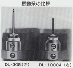
DENON has already released the DL-1000A, the highest grade cartridge, but in order to fully demonstrate the outstanding music playback capabilities of this DL-1000A, we have developed the AU-1000 as the highest model of step-up transformer. I did.
In order to boost the minute music signals sent from the cartridge, physical characteristics such as frequency characteristics were pursued, and countermeasures against external induction, i.e., strict shielding of the transformer unit and main unit, anti-vibration structure, connection cords, etc., were thoroughly examined in detail. and improved the degree of perfection.
In addition, in terms of sound quality, we have repeated sufficient listening tests to create a product worthy of the name of "the highest peak of step-up transformers."
Features
1. Basic design born from thorough pursuit of sound quality.
For the transformer core, under strict material management, special-shaped large permalloy thin plates that pass strict specifications are laminated . Magnetic permeability, which is the basis of transformer quality, is about 1.5 times higher than conventional products (compared to our company) in the bass range, and achieves high saturation magnetic flux density over the entire .
A special split sandwich winding reduces the line-to-line capacity and extends the high range. In addition, a primary winding that is about 1.4 times thicker than conventional products (compared to our company ) is used to reduce resistance loss. Combined with the high saturation magnetic flux density, the dynamic range is wide, realizing a rich sound reproduction .
2. Thorough pursuit of sound quality with a simple structure.
Since it is dedicated to the MC cartridge DL-1000A, the impedance selector switch and intermediate taps have all been eliminated, and the structure to improve sound quality.
3. Multi-shield structure that is resistant to externally induced vibration noise.
A single transformer is double-shielded with a permalloy shield case, put in a thick gunmetal case, and fixed with a filler. Also, since the LR channels are wired independently in separate gunmetal cases, there is no crossover of wiring. Furthermore , the entire body, including the input/output pin jacks, is covered with a thick casting shield case and can be used as a high-grade universal transformer.
I owned that maybe the best Denon cartridge ever and when I bougth the cartridge in Laredo, TX I did not know about the Denon SUT.
Here the DL 1000A ( btw, one of the J.Carr vintage cartridge favorities. ):
Main features of DL-1000A
■ We challenged the limits of weight reduction and achieved an astounding effective mass of 0.077mg.
The vibration system of the DL-1000A faithfully traces the complex and fine sound grooves, so a new material, New Amorphous Boron Pipe, is used to thoroughly reduce the weight of the vibration system, resulting in an effective mass of 0.077mg. realized. (DL-305 is 0.168mg) In
addition, coupled with light effective mass and well-balanced high compliance, extremely stable tracing is performed not only in the mid-low range, but also in the fine sound grooves in the high range. It is extremely rare to deform the sound groove. As a result, the playback band extends to an unprecedented ultra-wide band of 20Hz to 110kHz.
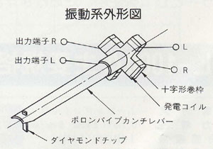
(1) High rigidity, ultra-thin and lightweight new amorphous boron pipe cantilever
DL-305 and DL-207 use amorphous boron, which is said to be the most ideal cantilever material and has a large specific rigidity. A cantilever with a thickness of 0.3 mm, a thickness of 0.023 mm, and a length of 4 mm is used.
(2) World's smallest micro stylus chip
Reducing the weight of the stylus tip, which is positioned at the forefront, has a great effect when reducing the effective mass seen from the tip of the stylus. It was considered very difficult to make a stylus chip micro, but we have improved our processing technology and accuracy to create a 0.06 mm square micro chip. (Approximately 1/2 of DL-303/305) The
shape is a special elliptical needle that has been precision machined.
(3) Uses a small cross-shaped winding frame and extra-fine copper wire
The cross-shaped winding frame can reduce the mass, and the left and right channel generating coils can be wound independently and symmetrically, and the dynamic balance during vibration is good, the sensitivity difference between the left and right channels is small, and uniform characteristics can be obtained. has two major advantages. The well-balanced generator coil uses ultra-fine copper wire, which advances the significant weight reduction of the vibration system.
(4) Like a feather. Stable tracing with record-friendly stylus pressure of 0.8g
The dramatic reduction in effective mass enables well-balanced, high-compliance, and a light stylus force of 0.8g shows sufficient tracing ability, providing stable tracing even for high-level cutting records. We will realize
(5) Flat ultra-wideband reproduction by 2-way damping system
In addition to broadening the bandwidth by reducing the effective mass, coupled with the adoption of DENON's original 2-way damper, flat frequency characteristics up to 110 kHz are realized, and reproduced sound with good energy balance can be obtained.
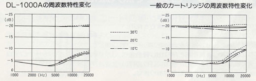
In addition, good temperature characteristics (small difference in sound quality between cold and warm regions) is another feature of 2-way damping that cannot be overlooked.
■ Powerful power generation structure
A samarium-cobalt magnet (with a magnetic energy product several times that of conventional magnets) is used in order to obtain a compact, lightweight, and strong air-gap magnetic field.
The weight of the cartridge has been reduced to 6g, but reducing the weight of the cartridge has the effect of reducing the effective mass seen from the position of the stylus of the tonearm, and the ability to follow the warp and eccentricity of the record. have a great effect on increasing
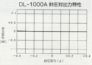
■ Emphasis on stylus pressure vs. output voltage characteristics
DENON attaches great importance to stylus pressure vs. output voltage characteristics as one of its basic performances.
The vibration system of the cartridge receives extra changes due to warpage of the record, etc., and the stylus pressure constantly changes. For this reason, if the linearity of the power generation system is poor, the output voltage will fluctuate greatly or be modulated, making it impossible to obtain a clear reproduced sound.
The DL-1000A has excellent linearity in the power generation system, and in combination with its excellent tracing ability, you can always obtain high fidelity and stable reproduced sound.
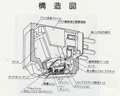
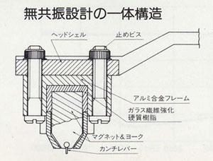
■ Promoting non-resonance with a strong frame structure
In order to fully demonstrate the performance of the excellent vibration system, we have adopted a strong frame structure that is non-resonant.
The frame, including the powerful magnetic circuit and output terminals, is made of hard resin containing glass fibers and a machined light alloy base.
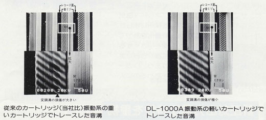
To amazing tracing ability
World's lightest - effective mass 0.077mg
The effective mass of the vibration system, which has been thoroughly refined and polished, has achieved the lightest weight of all cartridges, 0.077mg. At the same time, the world's largest dynamic compliance of 20 x 10-6 (static 50 x 10-6) cm/dyne is achieved. I just got amazing tracing ability. With this new dimension of tracing ability, you can reach the musical depths of record grooves that you could not reach before, and draw out all the musical information that could not be reproduced in the past.
■ Comparison of sound groove traces
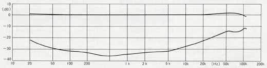
■ DL-1000A output voltage and crosstalk versus frequency characteristics
■ Comparison of frequency characteristics due to temperature change
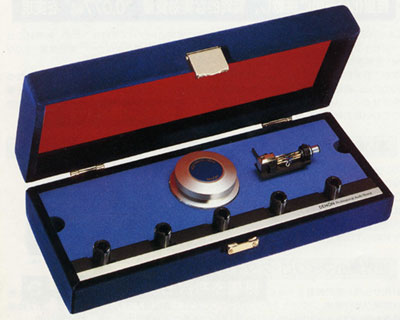
■ Cartridge case can be used as a cartridge keeper
The DL-1000A is delivered in a velvet-covered case. This case can store 5 cartridges with shells.
The stand on which the DL-1000A is installed can be used as an audio stabilizer after removing the cartridge.
In practice my SUT experience was disappointing. I used highly regarded Cinemag transformers with my Lyra Delos cartridge perfectly matched. The sound was energetic and loud but the treble was edgy and grainy.
Using my Sutherland 20/20 fully active without the SUT sounded much better.
SUTS are something you add if you do not want to purchase a good active phono preamp. My experience.
Dear @drbond : About quality level performance in SUTs the best regarded/build transformers are: the Hashimoto 7, the Altec 4722 and Tamura TKS83. Lundhall or Jensen are in a lower " league ".
Altec and Tamura are not in production any more, at least to my knowledge. Btw, the gentleaman behind HM-7 is Isao Asakura.
Denon choosed a special custom design Tamura transformers for the AU-1000 ( Denon use the standard Tamura in its AU-340 that I own too and modified too. ) and here what a true music lover and SUT expert said about ( he already tested the Lundhall, Jensen and others. ):
" HM-7 sound falls somewhere in between the organically detailed and dynamic TKS83 and the rich and spacious airiness of the classic 4722. "
No one of then are transformers silver wired but are the best of the best in SUTs.
Btw, the AU-1000 Tamura transformers are better than the others I named here. The Tamura in the AU-340 is the one reffered by that gentleman full comparisons.
In all subjective evaluation, one individual's selection of a Top Five is potentially the reject list of another individual.
It is the wonderful reason why the owners of systems that have built them up over time with selections made to meet each's unique preferences, are mainly all different assemblies of devices to perform quite similar roles.
Pumping Products are just that, products being pumped, they are not answers to what an individual is really attracted to and can quite easily prove to be a repellent to an individual.
This thread and many others within multiple forums are testament to how diverse the selections are that make up a system, which basically means Budget, Experiences, Attractors and Repellents are very much at play.
Experiences are where I encourage an individual to grow, with these under one's belt, the Budget required is beginning to be realised, the satisfaction that can be had through committing to a design/build that is an attractor, will certainly produce a customer who stands sure in their choices.
In practice my SUT experience was disappointing. I used highly regarded Cinemag transformers with my Lyra Delos cartridge perfectly matched. The sound was energetic and loud but the treble was edgy and grainy.
Using my Sutherland 20/20 fully active without the SUT sounded much better.
SUTS are something you add if you do not want to purchase a good active phono preamp. My experience.
I don’t doubt your experience. But I’m simply curious as to which "highly regarded" CineMag you tried? Quite frankly I found their 3440A (possibly their most common SUT) to be bad. I hope yours was at least a blue-label (better laminations) model other than the 3440 - they are MUCH better imo.
Every system & ear is different. Most will regard the MC stages of Herron VTPH-2A and Audio Research Reference 3SE to be at least "good", but in my system they both lose out to a well-selected SUT - for multiple MC cartridge brands & makes which I have in my collection. But you have to pick the "right" one! That goes for active MC stages, too.
I used highly regarded Cinemag transformers with my Lyra Delos cartridge perfectly matched. The sound was energetic and loud but the treble was edgy and grainy.
This is the tricky bit about SUTs. This sounds like a classic situation where the loading on the output of the SUT wasn't addressed. Depending on the cartridge's source impedance, the 47K load that was probably stock in the preamp was likely not correct. This can result in distortion and the interwinding capacitance of the transformer playing a role like a capacitor in parallel with the transformer.
So not only would the result be distorted (likely causing harshness) but it might not be flat either! I can imagine this being quite disappointing. At any rate if the loading were addressed I suspect this situation could have been rectified without replacing anything.
Dear @mulveling : SutherlaND 20/20 mk2 IS A VERY GOOD ss PHONO STAGE DESIGN ( LIKE THE pS aUDIO sTELLAR. ) AN YES BEEN an active high gain design just outperforms I think almost any SUT.
Here a review from 2011 and read it and please read carefully its measurements including the overload numbers and this Sutherland humble price tag as the PS Audio Stellar always be a challenge for any other phono stage surrounded by a good system:
I should be sure you have that RIAA deviation already measured and maybe you can share with us and your customers.
I'm hesitant to give you a measurement which you will certainly turn into a cudgel to use on me in the future but typical units are ± a third of a dB across the audio band.
Dear @mulveling : SutherlaND 20/20 mk2 IS A VERY GOOD ss PHONO STAGE DESIGN ( LIKE THE pS aUDIO sTELLAR. ) AN YES BEEN an active high gain design just outperforms I think almost any SUT.
I’m sure the Sutherland is a lovely MC stage. I get that it’s an active trans-impedance amplifier, different from my JFET MC stages or SUTs. At this point of my journey, I have no interest reading published reviews of gear.
What I’m not quite sure of is your angle here. Please let me know which of the following apply (check all that apply lol):
The JFET MC stages in the Herron VTPH-2A and my ARC Ref 3SE are not "good". If you recall, I prefer selected SUTs over both of these. (I’ve also had other JFET MC stages too, but these two are generally lauded as very good if not exceptional)
More generally, both voltage amplifiers and SUTs are not "good". Trans-impedance is the way
It’s actually my system and/or hearing that is not good :)
Dear @mulveling : For a LOMC cartridge in high gain nactive designs the device that conforms better electrically to MC cartridges are bipolars no JFET. So why almost all that kind of AHG designs use JFET? because bipolars are a " pain " to " handled " in that stage JFET is very easy on the design and is very good in dedicated MM stages.
No, transimpedance is not the way. Good current or voñltage designs makes excellent job. You have to think that in the last 40 years 99% of phono stages including the top ones are voltage designs with no compliants about and you don't need to care that the cartridge for a current unit needs to be very low internal impedance.
Time ago wpalmer that has true high knowledge levels in electronics due that he laborated for several years in Analog Devises as designer and group leader and posted this about:
"
I'm in the process of having a phono preamp made manufacturable by a well known audio company. The first thing they insisted upon was that the design would be implemented in SMD- purely for manufacturing purposes. This had it's own unique set of difficulties- for example, some of my preferred capacitors were not available on SMD, so a search for suitable items of a different technology (ceramic MLCC C0G vs Polypropylene film) was needed, together with a proof that the distortion characteristics were essentially equivalent.
The other aspect was that the preamp design investigated two possible implementations, either a voltage mode input, or a current mode input, and with the 75uS RIAA TC implemented in the first stage.
I ended up with a voltage mode input, as when designed for equivalent gain and RIAA characteristic there is, generally, no measurable or audible difference.
However, there are indeed differences in operation and implementation.
To put this somewhat in context, I designed a number of "transimpedance" amps while at ADI, most notably the AD846, together with a number of conventional opamps, so I am familiar with the concepts. The AD846 was designed to have almost perfect current conveyance properties and could be operated open loop as a transimpedance amplifier. Most opamps/amplifiers use negative feedback to achieve this goal, or have high distortion levels if operated open loop.
As I don't want to make this into a "white paper" I'll try to be brief.
1. A phono cartridge is a voltage generator (Vs) with an output impedance which is mostly a resistance in series with an inductance (R+Ls). This can be converted into the Thevenin equivalent current source- which is a scaled current (Vs/(R+Ls)) with the output impedance in parallel to ground.
If you take this current and drive it into a virtual ground, which shorts out the shunt components, and convey it to the load resistance (Rl) then the output voltage is Vs*Rl/(R+Ls). If Ls is small then the gain is completely dependent on the series resistance of the cartridge and will vary from cartridge to cartridge, and if LS is large there will be a HF roll off.
Any shunt capacitance will be essentially ignored.
If there is a resistor added in series with the virtual ground, then the current is shared between the equivalent shunt components and the series R, and the gain becomes even more variable.
Voltage mode lacks this complexity. Provided the load impedance is relatively large compared to R the gain is easy to determine.
However, the shunt capacitance is not ignored, but for MC cartridges the inductor is so small that all parasitic capacitance values are irrelevant, assuming the load R is small enough to damp out the LC resonance.
Current mode does not experience this resonance, but correct loading Rs plus a phono stage with a suitably good ultrasonic overload margin will take care of the potential problem.
MM cartridges into a virtual ground are not rational unless there is a very large resistor in series with the virtual ground. This is because the R is large but L is even larger.
2. In voltage mode the input stage is non-inverting and will experience potentially substantial deviations about ground. For many opamps, particularly earlier generations than the most recent ones, this voltage will cause increases in distortion due to the operating conditions of the input transistors being changed.
This distortion can be highly sensitive to the source impedance and the input signal level.
In the transresistance mode the virtual ground does not move, removing this source of distortion.
Modern audio IC opamps are generally designed with this problem in mind and exhibit negligible changes in distortion when operated in non-inverting mode.
These are the two main aspects of current versus voltage mode inputs.
There are other, more obscure, aspects.
I chose voltage mode, but also chose appropriate opamps to minimize the down side of the choice.
The bottom line is, when properly designed both current and voltage input designs can have equivalent performance from the perspective of distortion, frequency response etc.- but the voltage input design is more predictable and easier to specify.
The voltage input design produced has very precise gain, extremely precise RIAA compliance and unmeasurably low distortion. ""
From the last 2 years exist a " fever " for the current designs and obviously that the customers with unit that handled in both versions prefer teh current one and I understand it because they bougth that phono stage for the current design. For me is only a today fashion.
Dear @intactaudio : Appreciated. I think you know the critical importance of that FR RIAA deviations .
I’m way demanding here more than in other audio electronic issues, my unit measured 0.012 and in both channel measure chart you can’t identify the left from the rigth channel, so not only extremely precise but both channels mimic in between and no it’s not digital design but analog one with out inductors. Additional in my unit you can switch on/off for the Neumann pole.
You quote another post above: “A phono cartridge is a voltage generator (Vs)”
To me, that sounds like a premise, and from my very limited knowledge base, it sounds like it could very well be a false premise, as phono cartridges generally produce very low voltages, which would imply that they are indeed better classified as current generators….
if that’s the case, then all conclusions based on that premise are also potentially false.
well done @drbond you are onto something important here.
Wiki says…
…or conversely, an external time-varying magnetic field through the interior of the coil generates an EMF (voltage) in the conductor.
However… the wiki for Maxwell’s equations says, (under Ampere/Faraday)…
The original law of Ampère states that magnetic fields relate to electric current. Maxwell's addition states that they also relate to changing electric fields, which Maxwell called displacement current. The integral form states that electric and displacement currents are associated with a proportional magnetic field along any enclosing curve
That link to displacement current says:
In electromagnetism, displacement current density is the quantity ∂D/∂t appearing in Maxwell's equations that is defined in terms of the rate of change of D, the electric displacement field. Displacement current density has the same units as electric current density, and it is a source of the magnetic field just as actual current is. However it is not an electric current of moving charges, but a time-varying electric field. In physical materials (as opposed to vacuum), there is also a contribution from the slight motion of charges bound in atoms, called dielectric polarization.
Hence I think that Raul could be correct.
While I was pretty sure that a cartridge is a current generating device, I am not so sure anymore.
The statement of, “a time varying electric field” also explains why a transformer voltage does not vary much with load.
A speaker and a cartridge are not too dissimilar.
If we consider a speaker, and yell into it, then the movement of the cone, generates a movement of the voice coil, and a change of how it sits in the magnetic flux of the motor. And if we are hoarse we can push it with a finger tip.
if it was generating a voltage:
then when the speaker terminals are open, there is no load against the voltage, and whether we push on the cone with a finger or thumb, it should move freely.
And if we put a 2 ohm resistor across the speaker terminals then that voltage will need a lot more current as it moves, and the speaker should feel stiffer to the finger tip.
if it is a current generating device then:
The movement will generate a fixed current and in a shorted speaker it should easily pass the fixed current and the cone should feel limber
and with an open set of speaker terminals, then the cone will be trying to drive current into an infinite load and require the voltage to rise towards infinity and the speaker cone should feel stiff.
Dear @holmz : I was in a hurry when my post to op but I gone thinking that's the whole context what is behind what Palmer posted. He participated in that technical loading thread that after some posts took other road.
I can't remember but I think that in other threads you and he had a very interesting technically posts.
R
Thanks Sir.
Which Palmer, or what is their moniker?
It seems like we maybe venturing slightly off topic with respect to SUT and SQ, but perhaps it is related, as SUT are magnetic-electrical devices, as are cartridges, which seems to be primarily magnetic and secondarily electrical devices (if electromagnetism can even be split up like that), but here is an interesting overview of magnetism, which seems to indicate that current is more directly related to magnetic devices, as opposed to voltage, although both current (I) and Voltage (V) are related by ohms law V = IR:
“Magnetic flux and current go hand in hand, and they have the differences. When current is induced in an area there will be magnetic flux and this magnetic flux will be opposite to that of the normal flux.
Now there will be a coil where we will induce current into it and then we can see the production of a magnetic flux. we see that when there is current induced there will automatically be an electric field and magnetic field produced inside the coil. So now when there is both magnetic and electric field there will also be flux lines.
Magnetic flux is simply the quantity which measures the amount of magnetic force that passes through a unit area per unit time. The magnetic flux is generally the number of lines which usually pass through the given unit area.
Simplest terms, a magnetic flux is comparable with electrical current as well as a magnetization in which current plays a major role is comparable with electrical voltage.
Although there are significant distinctions, a magnetic circuit is comparable to an electrical circuit. Magnetomotive force is equivalent to electromagnetic force inside of an electrical circuit.”
Whether a cartridge is a 'voltage' or 'current' generator simply comes down to the load you present it with. Make the load an open circuit (volt meter) and it will deliver max voltage and essentially 0 current. Make the load a short circuit (ammeter) and it will deliver max current and 0 Voltage. Without a clearly established loading criteria, the discussion becomes one of futility.
Dear @drbond : I think that if some one as me and maybe you re-read the Palmer explanation where @holmz added several technical characteristics maybe you can be less " worried " about.
The amps explanation linkes is wider and as I said holmz expanded on it. Now, do you think that Palmer does not knowed all the theory behind about? , I'm totally sure that he knows but not only that he laborated with for over 20 years.
Now, maybe you have a " hide card " or you have a specific target behind your links. Good, but if you have dudes just contact that gentleman or even better and invite him to share other kind of technical explanations on the issue. Don't you think could be better?
Here’s my current assessment, which has been nicely summarized by @intactaudio : basically, the cartridge is naturally developed as a current generator, however for the past decades, phono stages were created to unnaturally transform the cartridge into a voltage generator by adding the load in the phono stage. However, when the cartridge operates as a current generator, no external arbitrary loading needs to be added to the signal created by the cartridge. So, it seems, based on my limited knowledge, that the current based phono stages would be most naturally associated with phono cartridges.
The SUT I used include Cinemag 1254 transformers wired at 1:10 for my Lyra Delos.
It sounded louder because of the extra resulting gain and really good but ultimately not as refined overall as my Sutherland fully active.
Thanks. There are better SUTs (for more money), but the 1254 is indeed a good one. I was afraid you were using a 3440 but that's not the case. A good mark for the Sutherland, indeed. I'll have to try one someday!
Btw, @intactaudio : you capacitance parameter of 80pf coukld be not real to make SUT measurements as the 300k load.
Normally what sees the MM stage + SUT is a load of 47k and capacitance around 200pf. Then measures arwe different that with your " choosed " parameters.
Unfortuntaelly cable manafucterer almost never gives the cable capacitance but almost all are higher than 150pf and even over 200pf.
You must have a verified phone number and physical address in order to post in the Audiogon Forums. Please return to Audiogon.com and complete this step. If you have any questions please contact Support.