Your latter post about preferring an integrated "phonolinestage" over separate phono and pre-amplifier would also logically favor an integrated pre-amplifier / amplifier over separate components, so I'm not so sure that your ideal preference holds true to real life experience.
SUT - electrical theory and practical experience
Some vinyl users use a SUT to enhance the signal of the MC cartridge so that it can be used in the MM input of a phono stage. Although I don't understand the theory behind it, I realize that a SUT should be matched individually to a particular cartridge, depending on the internal impedance of the MC, among other things.
Assuming an appropriately / ideally matched SUT and MC, What are the inherent advantages or disadvantages of inserting a SUT after the MC in the audio chain? Does the SUT theoretically enhance or degrade the sound quality? What does the SUT actually do to the sound quality?
Thanks.
I believe it is the field that “flows” around the conductor.
The electrons actually do flow, just not very fast.
They are not instantaneous, as the electric field propagates as the speed of light/dielectric constant. The electric field essentially pushes, or sweeps, the electrons along. The electric field can be super high, but with no current there is little or no magnetic field. And the voltage (electric field) can be super low, but have a massive current… and then we get little electric field and a huge magnetic field. in the devices we are considering the impedance is not zero like in a super conductor, nor it is it infinite… it is pretty constant. So there is a fixed proportionality between the voltage and current… and hence a fixed proportionality between the electric and magnetic fields.
There are all sorts of hypothesis as to why the metal choice might impart a different sound, but most are a bit light and fact and oversubscribed in magic. In a transformer, similarly it is possible that the core material is as important as the choice of wire used for the windings. In a “Field Effect Transistor” (FET) it is the electric field that controls the gate. | ||||||||||||||||||||||||||||||||||||||||||||||||||||||||||||||||||||||||||||||||||||||||||||||||||||||||||||||||||||||||||||||||||||||||||||||||||||||||||||||||||||||||||||||||||||||||||||||||||||||||||||||||||||||||||||||
A FET works more like a valve/tube. When that the SUT amplifies/increase voltage. Deficiencies: The SUT has resistance, inductance and some capacitance. And hence a finite bandwidth. But many transistors have capacitance effects that limit their bandwidth. And how high can one really hear?
If in doubt on the SUT, it may be better to slightly undershoot ratio, than to wildly overshoot the ratio… and especially if the cart has a high output impedance.
Correct one cannot tell the difference in speed by ear, but that point was in relation to your statement on copper versus silver wires. The dielectric also plays a role. In the SUT the core also play a bit of a similar role to the magnetic field, that the dielectric played upon the electric field.. It is not altogether clear, that one can easily tease out all the nuance.
Back to
The circuit designers all make good examples in each, so pick your poison. | ||||||||||||||||||||||||||||||||||||||||||||||||||||||||||||||||||||||||||||||||||||||||||||||||||||||||||||||||||||||||||||||||||||||||||||||||||||||||||||||||||||||||||||||||||||||||||||||||||||||||||||||||||||||||||||||
Hi @pindac , I’m agree that EAR834p has rich and bloat the lowest frequencies character. This character of the schematic remained despite improving bass resolution and dynamics, and more clean and open height frequencies in the better implemented version. Another factor are speakers. My Altec 604E speakers have dry bass. So it works good all together at least for my taste and for classical and jazz music that I like to listen. Regards, Alex | ||||||||||||||||||||||||||||||||||||||||||||||||||||||||||||||||||||||||||||||||||||||||||||||||||||||||||||||||||||||||||||||||||||||||||||||||||||||||||||||||||||||||||||||||||||||||||||||||||||||||||||||||||||||||||||||
The problem you are up against using either device above is that the input side of the device is outside of the feedback loop. You will have a rather prodigious electrical peak, likely between 1-5MHz with most LOMC cartridges. It might be as much as 30dB depending on the Q value (how long as opposed to how wide) of the coil in the cartridge. That peak can be energized and easily overload the input despite the use of feedback. So an SUT has the advantage of not being overloaded in this way and actually blocks the RFI generated in this fashion from reaching the phono stage input! That's a pretty clear advantage! (The overload can cause ticks and pops as well as distortion which is perceived as brightness- hence the use of 'cartridge loading' resistors, which detune the electrical resonance, preventing it from going into excitation.) If you're going to run solid state, you need to use an opamp to get around this problem, or set up the feedback look on the discrete devices in the same manner as used in with an opamp; essentially creating a low performance opamp in the process...
| ||||||||||||||||||||||||||||||||||||||||||||||||||||||||||||||||||||||||||||||||||||||||||||||||||||||||||||||||||||||||||||||||||||||||||||||||||||||||||||||||||||||||||||||||||||||||||||||||||||||||||||||||||||||||||||||
Hi @atmasphere , I have a question for you regarding the use of feedback in tube phonostage. Unlike a power amplifier, the frequency response of the RIAA implies a deeper feedback at high frequencies. Is this kind of feedback deep enough to work properly? Regards, Alex | ||||||||||||||||||||||||||||||||||||||||||||||||||||||||||||||||||||||||||||||||||||||||||||||||||||||||||||||||||||||||||||||||||||||||||||||||||||||||||||||||||||||||||||||||||||||||||||||||||||||||||||||||||||||||||||||
If in a discrete solid state circuit, maybe?? -a lot will depend on the semiconductors involved!! It can work OK with tubes, but if you really want to get it right, you run the amplification flat and use passive EQ. That way you can apply the feedback needed to do the job right. | ||||||||||||||||||||||||||||||||||||||||||||||||||||||||||||||||||||||||||||||||||||||||||||||||||||||||||||||||||||||||||||||||||||||||||||||||||||||||||||||||||||||||||||||||||||||||||||||||||||||||||||||||||||||||||||||
Dear @drbond : " would also logically favor an integrated pre-amplifier / amplifier over separate components, "
Not really, I am in favor that the amplifier stays as nearer the speaker as we can and that's why I use monoblocks with really short output cables that are soldered directly to the speakers external modified crossovers where each speaker driver frequency range has its dedicated crossover/cable that goes soldered directly to each driver.
No, what I'm in favor is for a Phonolinepreamp unit but separates amps.
R. | ||||||||||||||||||||||||||||||||||||||||||||||||||||||||||||||||||||||||||||||||||||||||||||||||||||||||||||||||||||||||||||||||||||||||||||||||||||||||||||||||||||||||||||||||||||||||||||||||||||||||||||||||||||||||||||||
One user recommended a particular search, and it supplied the following website, which I found very informative. Here is a copy from the first two paragraphs from a transformer manufacturer, Rothwell Audio Products: “the cartridge operating principle why use a transformer at all? | ||||||||||||||||||||||||||||||||||||||||||||||||||||||||||||||||||||||||||||||||||||||||||||||||||||||||||||||||||||||||||||||||||||||||||||||||||||||||||||||||||||||||||||||||||||||||||||||||||||||||||||||||||||||||||||||
Rothwell Audio is a Trusted Service. Their layman's technical descriptions on offer are very well worded and comprehensible. They are a reference point for all levels of knowledge in electronics relating to HiFi, and for some the first knowledge gathered when curiosity about the technical side of a particular device is being sought to be understood further. | ||||||||||||||||||||||||||||||||||||||||||||||||||||||||||||||||||||||||||||||||||||||||||||||||||||||||||||||||||||||||||||||||||||||||||||||||||||||||||||||||||||||||||||||||||||||||||||||||||||||||||||||||||||||||||||||
Yes, Rothwell Audio website seemingly very clearly and concisely explains even the basics of audio, as evinced by the next paragraph on impedance loading of cartridges, which can be applied to any component matching: ”cartridge loading | ||||||||||||||||||||||||||||||||||||||||||||||||||||||||||||||||||||||||||||||||||||||||||||||||||||||||||||||||||||||||||||||||||||||||||||||||||||||||||||||||||||||||||||||||||||||||||||||||||||||||||||||||||||||||||||||
….but, Rothwell Audio Products explanations also go into further detail in the next section, which would definitely imply caution against SUT use in a current based phono stage, due to geometrically increasing impedance: ”the transformer turns ratio and impedance ratio So, it would seem logical that a cartridge with an output voltage of, for example, 0.5mV, when used with a step-up transformer with a 1:10 turns ratio, would produce 5mV at the transformer’s output. Yes, it would if the cartridge’s source impedance (also known as its internal impedance or its coil impedance) was zero. In practice, with low impedance cartridges of about 10 ohms or less and low ratio transformers (less than about 1:20), the transformer’s output voltage is very close to the cartridge’s output voltage multiplied by the turns ratio and can be safely used as a good first order approximation for guidance. However, the cartridge’s source impedance may be low but it is never zero, and the transformed secondary load needs to be considered for a more accurate analysis. Consider as an example a transformer with a 1:10 ratio and a cartridge with a 10 ohm coil. If the load on the transformer secondary is an MM phonostage with a 47k impedance, that load appears to the cartridge as 470 ohms (47,000 divided by 10 squared) and must be driven by the 10 ohm coil. The 470 ohm load and the 10 ohm source form a potential divider (the “pre-set volume control” described in the previous section) with some of the cartridge’s voltage dropped across its own internal 10 ohm impedance. The proportion dropped internally is 10/(470+10) = 0.0208, which is not very much at all – just 0.2dB. The deviation from the first order approximation is small and probably not worth worrying about, but it is there. It’s when higher turns ratios are used with higher source impedances that the potential divider effect becomes significant. Consider a cartridge with a 40 ohm coil and a transformer with a 1:30 ratio. The 47k load on the secondary now appears as 52 ohms from the primary side. When driven by a 40 ohm source the voltage divider is formed by 52 ohms and 40 ohms. Therefore the proportion of signal dropped across the cartridge’s coil is 40/(40+52) = 0.43, which is very significant – nearly half the voltage produced by the cartridge is lost internally. Whereas only 0.2dB was lost in the previous example, here the signal loss is 5dB, and instead of achieving a signal voltage at the output of the transformer of 30 times the cartridge’s output, the output is only 0.43x30 times the cartridge’s output, ie a voltage step-up of effectively just 13 times, not 30 times. Clearly, increasing the transformer turns ratio by a factor of X doesn’t increase the output voltage by the same factor. As the turns ratio increases, the increase in the output voltage gets less and less as the load on the cartridge becomes more and more significant until a point is reached where increasing the turns ratio further actually causes the output voltage to drop. To demonstrate how far wrong the “matched impedance” approach can be, take as an example an Ortofon Vivo Red cartridge with a 5 ohm source impedance. In order to "match the impedance”, the 47,000 ohms on the secondary side of the transformer would have to appear as 5 ohms on the primary side. That means that the impedance ratio must be 9400 (because 47,000 divided by 5 equals 9400) and therefore the turns ratio must be the square root of 9400, which is 97. So we must find a step-up transformer with a turns ratio of 1:97. However, the Vivo Red’s output voltage is 0.5mV and the voltage fed to the phonostage by a 1:97 transformer would 24mV. That would be enough to overload most phonostages and would be a long way from optimal. A much better approach to finding a suitable transformer ratio would be to work with the cartridge’s output voltage. The Vivo Red has an output of 0.5mV and the phonostage requires about 5mV for the best performance, therefore a ratio of 1:10 would appear to be much better. The first order approximation suggests a 1:10 ratio would give us 5mV. Does that still hold true if we also consider the cartridge’s 5 ohm source impedance and the load impedance presented by the transformer? Yes. A 1:10 transformer with a 47k load on its secondary winding presents a load of 470 ohms to the cartridge. The voltage divider formed by the 5 ohm source impedance and the 470 ohm reflected load means that only 5/(470+5) is dropped across the cartridge’s internal impedance and the actual voltage at the transformer’s output is 4.95mV, ie extremely close to the estimate using the approximate method. The 470 ohm load seen by the cartridge is perfectly compatible with Ortofon’s recommended load of >10 ohms. The “impedance matching” method of using a 1:97 ratio transformer would give the cartridge a 5 ohm load impedance, which is outside the manufacturer’s recommendation. Also, for the reasons explained below, a 1:97 transformer would have a seriously compromised performance compared to a 1:10 transformer. Now consider a different cartridge, the Dynavector Karat17D3 with a 38 ohm coil. Using the impedance matching approach to find the best transformer ratio we end up with a ratio of 1:35 and the cartridge’s 0.3mV output becomes 5.25mV at the the transformer’s output. This time, the “impedance matching” approach appears to have worked out well, but is is really the best turns ratio? Maybe not, because Dynavector’s recommended load is 100 ohms and a 1:35 transformer would give the cartridge a 38 ohm load. In this instance a lower turns ratio would be better. For example, a 1:20 transformer would give the cartridge a load of 117.5 ohms and have an output of 4.5mV. Also, a 1:20 transformer is likely to have better performance than a 1:35 transformer, as explained below.” | ||||||||||||||||||||||||||||||||||||||||||||||||||||||||||||||||||||||||||||||||||||||||||||||||||||||||||||||||||||||||||||||||||||||||||||||||||||||||||||||||||||||||||||||||||||||||||||||||||||||||||||||||||||||||||||||
Dear @drbond : Can you share which is your target with all those internet links you posted? Btw, every one but you knew the Rothwell information because it was posted several times in several other threads over many years now. Do you think that are discovering the " black thread " ? Please, wake up.
R. | ||||||||||||||||||||||||||||||||||||||||||||||||||||||||||||||||||||||||||||||||||||||||||||||||||||||||||||||||||||||||||||||||||||||||||||||||||||||||||||||||||||||||||||||||||||||||||||||||||||||||||||||||||||||||||||||
@drbond Making the Rothwell info' available in the extended version as presented is quite fitting. This thread is certainly a place worthy of their descriptions being found. As providers of a Design for a Step-Up Transformers along with their Head Amp Design, they do provide very useful information for any level of understanding to consider. I am sure the presentation from them wins favour with customers. As seen in various posts, not all are using Step-Ups from the same Brands, and Step Ups are to found ranging from £$200ish through to £$3000ish and maybe upward if the Ikeda and MSL models are of interest. The next SUT's of interest for me fall into the £500+ area depending on Spec and Coil Wire, I don't see over the £1K being of interest, but a bespoke built from the Brand will comfortably surpass this. It does look to be a very competitive market to maintain the greater slice of the Pie Chart. | ||||||||||||||||||||||||||||||||||||||||||||||||||||||||||||||||||||||||||||||||||||||||||||||||||||||||||||||||||||||||||||||||||||||||||||||||||||||||||||||||||||||||||||||||||||||||||||||||||||||||||||||||||||||||||||||
People try to lump all kinds of technical truths into simple rules of thumb which then become the norm. After being accepted, the underlying truths these norms are built upon tend to get lost. The three main things that need to be considered when designing / implementing a SUT are Impedance (source and load), gain and loading. While all three of these items are interrelated by math, they all need to be addressed (juggled) individually. The source / load impedances are what determine the required primary inductance and the winding geometry required to get the desired bandwidth. What needs to be done for a 2Ω cartridge is different than what is needed for a 40Ω cartridge. The turns ratio is set to elevate the cartridge output to the desired input of the phono stage it is driving. A 0.25mV output 40Ω Denon 103 roughly fits the same impedance numbers as a 24Ω 1.0mV EMT but requires a different turns ratio. Loading is the the part that gets way too much emphasis and really should be only a minor part of the consideration. The focus on cartridge loading as a primary concern causes much confusion and turns what should be a very simple process into a black art. There are two aspects to the reflected load, the resistive part and the capacitive part. The resistive part sets the actual reduction of gain from the ideal. Attention must also be given to the load capacitance as the turns ratio increases since that value can quickly truncate the top end. I always consider the reflected load to be a liability and feel that using a transformer to reflect a desired load is misguided at best. People tend to consider the transformer as an ideal device that will perfectly reflect the terminating load to the primary. In reality this is far from being the case. More often than not, adjusting the secondary load to reflect back a desired value to the cartridge will have both a measured and a perceived effect on the performance of the SUT. It is this change that people incorrectly attributed to the load the cartridge is seeing. All transformers will reflect a minimum load based on the math and the goal should be to keep that number as high as possible. Increasing the 47kΩ input resistor values is a good place to start. Once the minimum load is determined, if additional loading is deemed necessary it should then be added to the cartridge directly where it will have a minimal effect on the behavior of the SUT but can have a dramatic effect on the tracking behavior (ie sonics) of the cartridge. dave | ||||||||||||||||||||||||||||||||||||||||||||||||||||||||||||||||||||||||||||||||||||||||||||||||||||||||||||||||||||||||||||||||||||||||||||||||||||||||||||||||||||||||||||||||||||||||||||||||||||||||||||||||||||||||||||||
Dear @holmz : " There are all sorts of hypothesis as to why the metal choice might impart a different sound, but most are a bit light and fact and oversubscribed in magic.
Dielectric, yes I think with out facts its importance as a wire insulator and with out facts too the qualitlevel of the of the cooper/silver wire. @intactaudio audio that were posting in the thread can put some " ligth " about because he manufacture SUT either: cooper or silver and normally his customers prefer silver material over cooper. So, Dave hopefully you can share your know-how and experiences about.
R. | ||||||||||||||||||||||||||||||||||||||||||||||||||||||||||||||||||||||||||||||||||||||||||||||||||||||||||||||||||||||||||||||||||||||||||||||||||||||||||||||||||||||||||||||||||||||||||||||||||||||||||||||||||||||||||||||
As @intactaudio points out, loading is another aspect of the SUT, and this is where, based on my limited reading, things seem to start to get complicated. Here is what Rothwell Audio's website says about transformer loading: "transformer loading | ||||||||||||||||||||||||||||||||||||||||||||||||||||||||||||||||||||||||||||||||||||||||||||||||||||||||||||||||||||||||||||||||||||||||||||||||||||||||||||||||||||||||||||||||||||||||||||||||||||||||||||||||||||||||||||||
For those who don’t mind clicking links, and are interested in reading more, here is the link to the informative, educational page from Rothwell Audio Products, and they do mention use of different materials, such as copper vs silver somewhere on the page, although their experience may differ from others: http://www.rothwellaudioproducts.co.uk/html/mc_step-up_transformers_explai.html
| ||||||||||||||||||||||||||||||||||||||||||||||||||||||||||||||||||||||||||||||||||||||||||||||||||||||||||||||||||||||||||||||||||||||||||||||||||||||||||||||||||||||||||||||||||||||||||||||||||||||||||||||||||||||||||||||
@intactaudio has already stated "In fact assuming the frequency response safely covers the audio band, I find core material, dielectric choice and winding wire to be far more dominant factors in the final sound. I find extending bandwidth (particularly at high frequencies) is simply more icing on an already delicious cake". I have no issues with this Statement, I have had specific type Transformers Hand Produced for owned devices and have been involved in the dialogue between the EE Designer/Builder and their supply chain Tranx producer. There is indelible recollection of use of the construction materials as well as the Math involved. "if Intact Audio and Rothwell are in conflict, go with the former authority". There is more than one road to Rome. Rothwell are seemingly ubiquitous in their support and have available devices that can be used in conjunction with a Typical Cartridge Design, at reasonable/competitive cost to enable an interested individual to get on board and share in the experience. Intactaudio are quite different, the device on offer is Bespoke Built and Designed to be an Optimised Interface. The end user is quite sure about the choices for Cartridge and the supporting ancillaries they choose to use in conjunction to create the Phono Signal Path. Additionally, the end user is quite sure who's experience they want to assist with producing their Bespoke Built devices. I get the idea of approaching Intactaudio, it is not a strange approach or a pursuit of a luxury item. The approach is made with a intention to have the best support put in place for the Luxury Items. If one has a TT>Tonearm>Cart'>Phonostage at approximately £$20 000. If a further ancillary is attractive to be used in conjunction with the System, why would a Bespoke Built device not be a consideration. I've been having Bespoke Built Devices produced for 25 Years+, where I have relied totally on an EE's Experience and Skills and their supply chain, to bring the idea to a realisation. I do not feel short changed in anyway. In the earliest days, if I were to also include a Design Service and have a Blingy Encasement produced, I may have started to feel a little out of pocket. There are many nice enclosures 'off the shelf' on offer today, so this is not an issue of concern anymore.
| ||||||||||||||||||||||||||||||||||||||||||||||||||||||||||||||||||||||||||||||||||||||||||||||||||||||||||||||||||||||||||||||||||||||||||||||||||||||||||||||||||||||||||||||||||||||||||||||||||||||||||||||||||||||||||||||
from rothwell...
Lets say for example the goal is to load a cartridge @ its internal impedance. I agree with Rothwell that heavily loading down the secondary of a SUT to reflect the desired load to the cartridge is a mistake. However.... One could simply accept the 47kΩ termination on a 1:36 will reflect back 36Ω. In order to reduce the cartridge load to 5Ω, simply parallel a 5.8Ω resistor with the cartridge. (it is kinda cool how 36^3=47K) I have done this experiment and can emphatically state that in this case 5Ω≠5Ω. In the case with the load applied through the transformer it seems like a blanket has been thrown over the speaker. This is the exact "thick" sound people report from this type of loading. The error all too often made is incorrectly attributing the sound of the reflected load to the cartridge when it is actually the sonic nature of the loaded transformer. Simply doubling the turns ratio of the SUT and then loading the cartridge at the same 5Ω nets a very different sonic result. Thick, dark and muddy are the last terms I would use as descriptors. To complete the circle on this I have then taken a transformer loaded Jfet based head amp and compared the same cartridge above loaded at 47kΩ and at its internal impedance and I would say the overall pattern of sonic character followed that of the transformer with the additional load placed on the cartridge directly and the sound of the "traditional" heavily loaded transformer secondary is the outlier. dave | ||||||||||||||||||||||||||||||||||||||||||||||||||||||||||||||||||||||||||||||||||||||||||||||||||||||||||||||||||||||||||||||||||||||||||||||||||||||||||||||||||||||||||||||||||||||||||||||||||||||||||||||||||||||||||||||
@intactaudio Your last response is what I would call an IP reveal and very generous as an offered information. I carry info' like this from my Bespoke Designs I own,but have always felt my liberty was best constrained when the opportunity arose for sharing the Designer/Builders IP. I once had an awkward conversation with a not very well known to me EE at an event where I was demonstrating a device, they were keen for me to allow them to remove a Chassis bottom plate and let them see inside. I was adamant that that would be quite a betrayal to the designer with whom I have developed a close to 30-year friendship. | ||||||||||||||||||||||||||||||||||||||||||||||||||||||||||||||||||||||||||||||||||||||||||||||||||||||||||||||||||||||||||||||||||||||||||||||||||||||||||||||||||||||||||||||||||||||||||||||||||||||||||||||||||||||||||||||
Some observations: I always found the specs for a cartridge confusing: 0.25mV output at 5 cm/second. Into which load? Open circuit? Load=Cart impedance? Load=recommended impedance? Why not state the output voltage and the impedance at which it is measured? Most recommended load impedances are specified over a large range (100Ω-1K), and they are all usually 10x the cart source impedance so the voltage divider effect will be small, but in some cases, it could have a significant impact on the output.
Matching the cart source impedance into the load would only be relevant if you are trying to transfer the maximum power from source to load which is not the goal of a phono preamp. It would be like trying to match the load a speaker presents to the output impedance of an amplifier which can have an output impedance measured in milli-Ohms.
What you do want to match between cart and load is the conjugate match of the imaginary (reactive) part of the impedance so the cart sees a purely resistive load. The cart has a complex source impedance which may not be a simple series or parallel capacitive or inductive component but a combination of those elements. The complex impedance will most likely change with frequency as well, complicating the matching network calculations.
Perhaps what is needed is an S-parameter measurement file for the cart that can be used in a linear simulator to design an appropriate conjugate matching network. Most RF devices are spec'd this way and is the only practical way to design matching networks that work; absent this data, it's like trying to find your way out of a maze with your hands tied behind your back and wearing a blindfold. | ||||||||||||||||||||||||||||||||||||||||||||||||||||||||||||||||||||||||||||||||||||||||||||||||||||||||||||||||||||||||||||||||||||||||||||||||||||||||||||||||||||||||||||||||||||||||||||||||||||||||||||||||||||||||||||||
Dear @intactaudio : Thank's. I understand that normally the dielectric in SUT is air but I can be wrong. The only SUT silver wired I tested in my system vs SUT's cooper wired was the Audio Note Kondo that was compared vs the AT 1000T, Denon 340 and Denon AU-1000 and in all tests I prefered the cooper wired SUTs ( phono input 100k. ) and you the silver wired ones.
Maybe the SUT kind of wire is more or comes along with the room/system and owner targets. Different with speaker croosover inductors where silver is superior to cooper wired and ribbon shape over rounded ones.
Btw, the Kondo goes down to 2hz ! ! and Audio Note builded around the end of the 70's a SUT with an exceptional FR: 2hz to 200khz at -o.5db and 0.001% distortion. I never seen in the market and I don't know neither if was silver wired but probably not because was at the midle of Audio Note SUT line.
R.
| ||||||||||||||||||||||||||||||||||||||||||||||||||||||||||||||||||||||||||||||||||||||||||||||||||||||||||||||||||||||||||||||||||||||||||||||||||||||||||||||||||||||||||||||||||||||||||||||||||||||||||||||||||||||||||||||
This Thread with the content on SUT's has served as a very valuable and relevant thread for anybody with a curiosity about the method to be used with a MC Cartridge. There has been very valuable Posts contributed to this Thread and if read in Conjunction with the SUT Thread that resurfaced as this thread has developed is potentially a reference place for subjective evaluations and guidance on how a inclusion of a SUT might be perceived. For the record, I have been influenced by Copper Wire over Silver Wire, for all interface cables s and Transformers used in my system. I have had a period of using a Silver OCC Wire Phono Cable, but this is now Superseded with a Copper Wire Cable. I even had two very heavily modified CDP's trialed where the main differences were that one model was with Bespoke Produced Silver Tranx's and the other Copper. I was quite impressed with the Copper, and it was this design that was instrumental in my consideration of a CD source in my system. More recently I was being demonstrated Two SUT's in another system, one with Copper Wire Windings and produced to be an ideal match for a Miyajima Cart'. The other a usable match for the Cart' with Silver Wire Windings. I thought I was done on the SUT front and was where I wanted to be, with the EAR TX4 (The Head) being the Holy Grail to aspire to. What was experienced was beyond what was expected. I was blown away by the demonstration of both SUT's, as were the other attendees, of which a few have the opportunity to receive demonstrations of (The Head) in the system in use. Their assessment being there are similar impressions being made and it would be great to hear The Head and these Models A/B compared. Not many models would be considered as a contender. A SUT that is an ideal match for a Cart' is quite something and to have the Brands Models demonstrated in my own system in a winding ratio that is a match for my Cart', along with the Silver Wire version is the Top of the List for when I have a Vinyl Source back in action. | ||||||||||||||||||||||||||||||||||||||||||||||||||||||||||||||||||||||||||||||||||||||||||||||||||||||||||||||||||||||||||||||||||||||||||||||||||||||||||||||||||||||||||||||||||||||||||||||||||||||||||||||||||||||||||||||
| Post removed | ||||||||||||||||||||||||||||||||||||||||||||||||||||||||||||||||||||||||||||||||||||||||||||||||||||||||||||||||||||||||||||||||||||||||||||||||||||||||||||||||||||||||||||||||||||||||||||||||||||||||||||||||||||||||||||||
| Post removed | ||||||||||||||||||||||||||||||||||||||||||||||||||||||||||||||||||||||||||||||||||||||||||||||||||||||||||||||||||||||||||||||||||||||||||||||||||||||||||||||||||||||||||||||||||||||||||||||||||||||||||||||||||||||||||||||
Dear @phoenixengr : If LOMC cartridges are almost no sensitive to load impedance then which your real point that I don’t understand for sure and which is your solution and advantages on the cartridge quality level performance?
For some years in my system the active high gain phono stage came with a 100 ohm input resistor and through all those years I had not any single trouble ( that I been aware of. ) with several and different LOMC cartridges that I owned and own.
" recommended load impedances are specified over a large range (100Ω-1K), and they are all usually 10x the cart source impedance so the voltage divider effect will be small, but in some cases, it could have a significant impact on the output. "
Ly ra states that load range with its different cartridge models and Ortofon says over 10 Ohms even that its cartridges internal DC resistance is 7 Ohms. Clearaudio even does not gives any advise and in all its LOMC models the internal cartridge impedance is 50 Ohms and I tested the Goldfinger in my phono stage with n very good cartridge quality levels. I owned/own the Discovery and Insider Gold that came with the same internal impedance and again I had no trouble with even that in the past the Clearaudio advise was over 500 ohms ( 10x ) and that I remember that input resistor was not changed but before my today phonolinepreamp I owned the Classé DR-7 that is an active high gain design too and performed very well with that same resistor value.
So other that a change in SPL which is that " significant impact on the output generated by the cartridge not by the phono stage it self but the cartridge that’s what you and me( I understand ) are talking about. Your answer is appreciated. Always is time to learn for all of us.
R.
| ||||||||||||||||||||||||||||||||||||||||||||||||||||||||||||||||||||||||||||||||||||||||||||||||||||||||||||||||||||||||||||||||||||||||||||||||||||||||||||||||||||||||||||||||||||||||||||||||||||||||||||||||||||||||||||||
My point about the specified impedance along with the output voltage was to make the necessary gain calculations easier. In your Lyra example, using a 10 Ohm load with a 7 Ohm impedance cart will drop the output level by 4.6dB, which could be significant. The output level will only be insensitive to the load if the load is 10x the cart impedance or higher.
My point about conjugating the imaginary (reactive) impedance of the cart is to cancel out any inductive or capacitive reactance so the cart sees a purely resistive load which will give the flatest frequency response with no peaking at high frequencies. If the complex impedance of the cart could be measured or calculated, then the proper termination could be easily determined instead of guessing or by changing loads and listening for a difference. | ||||||||||||||||||||||||||||||||||||||||||||||||||||||||||||||||||||||||||||||||||||||||||||||||||||||||||||||||||||||||||||||||||||||||||||||||||||||||||||||||||||||||||||||||||||||||||||||||||||||||||||||||||||||||||||||
If you never tried any load other than 100 ohm, then you cannot know if there was a problem due to loading at 100 ohm . | ||||||||||||||||||||||||||||||||||||||||||||||||||||||||||||||||||||||||||||||||||||||||||||||||||||||||||||||||||||||||||||||||||||||||||||||||||||||||||||||||||||||||||||||||||||||||||||||||||||||||||||||||||||||||||||||
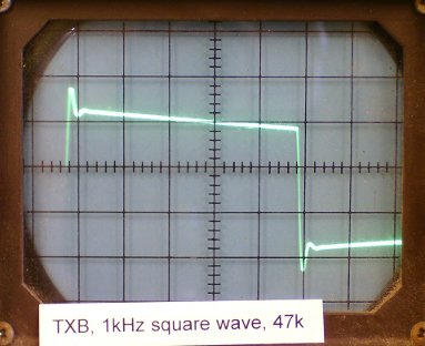
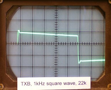
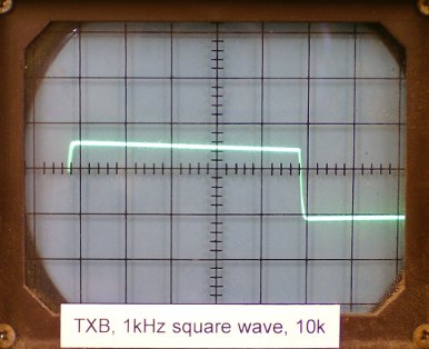
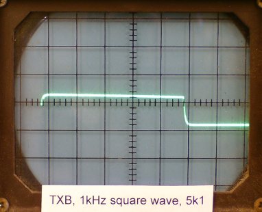
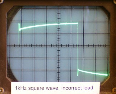
Flattest frequency response or best square wave ? Are these codependent ? With Jensen SUT's that are designed to be used with a zobel network they suggest adjusting the network to the source load by scoping a square wave. | ||||||||||||||||||||||||||||||||||||||||||||||||||||||||||||||||||||||||||||||||||||||||||||||||||||||||||||||||||||||||||||||||||||||||||||||||||||||||||||||||||||||||||||||||||||||||||||||||||||||||||||||||||||||||||||||
@dover ^thanks!^ I suppose I should ask where does one get the square wave track from? | ||||||||||||||||||||||||||||||||||||||||||||||||||||||||||||||||||||||||||||||||||||||||||||||||||||||||||||||||||||||||||||||||||||||||||||||||||||||||||||||||||||||||||||||||||||||||||||||||||||||||||||||||||||||||||||||
Ah! I forgot about being shown a Square Wave by the EE producing the Phon'. From recollection this Scope Reading was shown in conjunction with the 'mv' output per channel as a valuable reading to be assessed. I don't get too bogged down in such a presentation, I am trusting in the EE and their abilities, if they are claiming there is something present that is impressive and of value to the electronic function of the device, who am I to nit-pick at their explanation. The follow up listening has always been where I do my evaluations, and decide how much monies are to be removed from one's account, to achieve the experience permanently. | ||||||||||||||||||||||||||||||||||||||||||||||||||||||||||||||||||||||||||||||||||||||||||||||||||||||||||||||||||||||||||||||||||||||||||||||||||||||||||||||||||||||||||||||||||||||||||||||||||||||||||||||||||||||||||||||
Dear @dover : Yes I did it during the " thousands " of tests with the prototypes of the phonolinepreamp and through measures and listening tests the only parameter we can been aware was changes in SPL but not in FR but additional to that normally LOMC cartridges come with the " rigth " internal resistance to work very good looking those 100 ohms. Clearaudio is something espcial with those 50 Ohms.
R. | ||||||||||||||||||||||||||||||||||||||||||||||||||||||||||||||||||||||||||||||||||||||||||||||||||||||||||||||||||||||||||||||||||||||||||||||||||||||||||||||||||||||||||||||||||||||||||||||||||||||||||||||||||||||||||||||
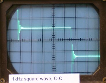
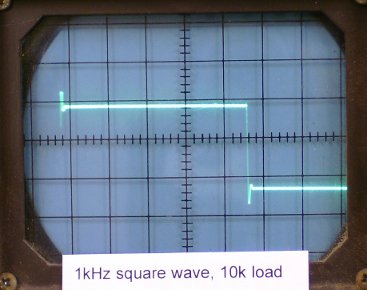
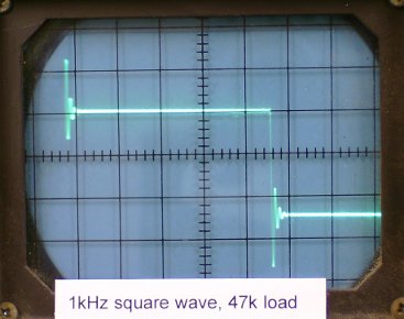
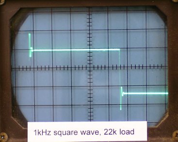
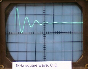
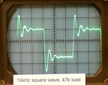
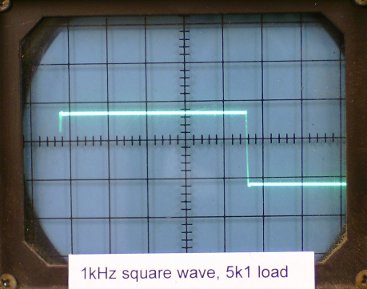
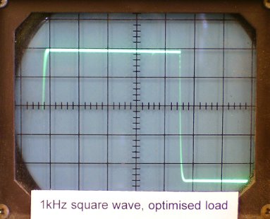
While I'm not certain, I think @dover may be referring to the reaction of the square wave to various loading, resistance, and capacitance properties, when dealing with SUT, which is found on that same Rothwell Audio Products site: "
" | ||||||||||||||||||||||||||||||||||||||||||||||||||||||||||||||||||||||||||||||||||||||||||||||||||||||||||||||||||||||||||||||||||||||||||||||||||||||||||||||||||||||||||||||||||||||||||||||||||||||||||||||||||||||||||||||
Dear @phoenixengr : " My point about the specified impedance along with the output voltage was to make the necessary gain calculations easier. " I was very clear and stated that my phonolinepreamp is an active high gain design and I can tell very good design or at least competitive today. Why should I care about gain when here I explained and told you that " other that SPL changes " whic other advantages? and I posted that we had not changes in FR. I'm not talking of phono stage + SUT.
R. | ||||||||||||||||||||||||||||||||||||||||||||||||||||||||||||||||||||||||||||||||||||||||||||||||||||||||||||||||||||||||||||||||||||||||||||||||||||||||||||||||||||||||||||||||||||||||||||||||||||||||||||||||||||||||||||||
Dear @holmz : In the good old times cartridge reviews where really great with all the information you can imagine. Here the LOMC Ortofon MC2000 ( that I owned ), page 83: https://worldradiohistory.com/Archive-All-Audio/Archive-Audio/80s/Audio-1984-12.pdf
R.
| ||||||||||||||||||||||||||||||||||||||||||||||||||||||||||||||||||||||||||||||||||||||||||||||||||||||||||||||||||||||||||||||||||||||||||||||||||||||||||||||||||||||||||||||||||||||||||||||||||||||||||||||||||||||||||||||
There are plenty of MC's up to 40 ohms ( eg Benz, Dynavector, Sony to name a few ) for which 100 ohms loading in my view is killing the cat. If your phono linear were stable you would be able to load at any value. It would seem that any observations or cartridge evaluations posted by you with this phono stage would be jaundiced by improper loading. | ||||||||||||||||||||||||||||||||||||||||||||||||||||||||||||||||||||||||||||||||||||||||||||||||||||||||||||||||||||||||||||||||||||||||||||||||||||||||||||||||||||||||||||||||||||||||||||||||||||||||||||||||||||||||||||||
Dear @dover : Yes, is totally stable. Now, till today 7-8 other owners never reported issues about and satisfied with their units. A " trouble " with the phonolinepreamp is that any load resistor change means to unsolder/solder the new one and to do that we have to open/take out the top plate and make the job carefully because the boards are 4 layers and we have to make 2 changes because is a dual mono design. During the unit presentation/show in USA I was at around10 different room/systems with different cartridges with no compliant for the system owners. I was not the designer engeenering in chief but I learned a lot down there and maybe theory not always works as should be depending of the kind of design. Rigth now I have not a clear explanation why performs so well against the 10x load other than minor SPL changes where noise level is no issue due that the unit has very low noise and distortion levels. The audio friends at my place with their own cartridges almost always were " impressed " by what their cartridges showed here through this phonolinepreamp. Jaundiced? you can be sure that’s not that way: theory vs real facts, including measures during prototype tests. In my vitual system says: " current mode " design ( what José stated. ) that comes from around 15 years ago and perhaps not estrictly " current mode " by today standards or a current mode " variation ". The issue is that works in excellent conditions over any " scenario ".
I can remember very clear that when I was showing it in Houston at a top Agoner and today reviewer ( he owns Rockport TT , Acapella Triolon’s, JC-1’s, ) that his Lyra was out of work in the same just time he was showing his system in its dedicated room and when the Lyra " hit " the first LP grooves he took in count that the Lyra was with out stylus : just disappeared and then we chage it by a Clearaudio he owned and we made the set up in his Rockport and he was really " surprised " for what he listened through my unit ( yes 100 ohms resistor ). Here what he posted: Audiogon Discussion Forum and this the first time down there: Audiogon Discussion Forum this gentleman with a Ruby2 in a Triplanar.
This the first version of the unit and VDH cartridge: another ones: and I can go on andd on. Lewm owns a 3160 and mine is the 3180.
Other cartridges as the Magic Diamond in a Walker TT in Phuladelphia with 15-20 listeners including Lloyd Walker him self and other presentation in San Diego with 15-20 listeners at an Audio Salon big audio distributor. Different cartridges same " resistor ".
R.
R.
| ||||||||||||||||||||||||||||||||||||||||||||||||||||||||||||||||||||||||||||||||||||||||||||||||||||||||||||||||||||||||||||||||||||||||||||||||||||||||||||||||||||||||||||||||||||||||||||||||||||||||||||||||||||||||||||||
In Georgia with Aolivero he owns the Proteus, Dallas with Albert Porter the 47 Labs, with the group in San Diego Lyra Skala and in the same area a gentleman with all Air Tigth electronics and with Air Tigth cartridge too. Other cartridge Allaerts and over there in a shoo-out vs Dartzeel with 3 different cartridges the owner of this unit made one load impedance change that in the Dartzeel and in the Essential nothing change and even the owner prefered ( not night and day differences. ) the Essential. In other place Dougdeacon with the Universe II and in Boise the Lyra Olimpos. I can't remember the cartridge at @sbank place . Dover, have you an explanation?
R. | ||||||||||||||||||||||||||||||||||||||||||||||||||||||||||||||||||||||||||||||||||||||||||||||||||||||||||||||||||||||||||||||||||||||||||||||||||||||||||||||||||||||||||||||||||||||||||||||||||||||||||||||||||||||||||||||
Propa P***ing Match now in the making. It's all about the Bass about the Bass is knocked well out of the Ballpark, and the next Pitch is "What about Me, I don't like SUT's", I want to ruin this discussion with my usual BS. What a waste of a Good Thread, SUT Discussion well and truly of the rails for a while, I'm out of here.
| ||||||||||||||||||||||||||||||||||||||||||||||||||||||||||||||||||||||||||||||||||||||||||||||||||||||||||||||||||||||||||||||||||||||||||||||||||||||||||||||||||||||||||||||||||||||||||||||||||||||||||||||||||||||||||||||
Dear @holmz : What Dover posted. You can read the link rigth from the Ortofon cartridge/SUT specs and then the measured sqare wave.
R. | ||||||||||||||||||||||||||||||||||||||||||||||||||||||||||||||||||||||||||||||||||||||||||||||||||||||||||||||||||||||||||||||||||||||||||||||||||||||||||||||||||||||||||||||||||||||||||||||||||||||||||||||||||||||||||||||
it would have been handy to have a physical triangular wave - cut into the track… and then everyone would be able to generate the square wave without needing a signal generator, | ||||||||||||||||||||||||||||||||||||||||||||||||||||||||||||||||||||||||||||||||||||||||||||||||||||||||||||||||||||||||||||||||||||||||||||||||||||||||||||||||||||||||||||||||||||||||||||||||||||||||||||||||||||||||||||||


