If you can post a picture of the power selection board, maybe I can provide some help on the voltage conversion.
BTW, have you completed the A-48 conversion?
BTW, have you completed the A-48 conversion?
Thank you, imhififan. Here's a picture of E-650: https://onedrive.live.com/?cid=6E164E2EDFDD40F6&id=6E164E2EDFDD40F6%2167223&parId=6E164E2EDFDD40F6%21120&o=OneUp Yes, I have completed the A-48 conversion. You've been very helpful. Thank you very much again! |
Hello @imhififan @foolishman just to be crystal clear, connector K3 needs to be moved to K5 and connector K4 moved to K6 as pictured here? https://i.imgur.com/inGH8JLh.jpg Sorry to be dense, but I want to make absolutely sure before having my tech do this. |
@eugene81 Your link to the picture doesn’t work. Is your board similar to this one? https://tsuf4g.ch.files.1drv.com/y4pqy67e0jerv5cTcb-Fc8_ipC-EI1w1ykz_wR1ZBK_94kZcjKZQGJV5K16_Rt6XGkm... Please upload your picture to your system page and provide a link. |
@imhififan Yes, that's the board. Sorry, let's try this again: https://photos.app.goo.gl/qknm4Js8Pe2t58rR9 https://systems.audiogon.com/systems/3753#&gid=1&pid=1 |
https://photos.google.com/share/AF1QipOGrOpMMqsYdBSgXH2RZ5WAQr8ECpSKQ9lZeFPP-kK9lqHx94MR8pkv-HWnDXZq... connector K3 needs to be moved to K5 and connector K4 moved to K6 as pictured here? Yes. |
I went ahead and did this myself and tested successfully with a dim bulb tester. The amp sounds fantastic! It is somehow both crisp and clear, yet rich and slightly warm, with great texture and soundstage depth. For others who might use this thread for reference, here are some more photos of the board removed, ready to work on, and post-conversion: https://photos.app.goo.gl/7rQ1gaZM6zDN1E47A Initially I thought it was one big board so I was going to take it to a pro. After being turned down by my usual tech (turns out they are an authorized Accuphase repair center and thus were told by Japan they couldn’t do it), I took another look under the hood and found that the connectors are actually on a smaller board secured by just 3 screws. I unplugged the 2 harnesses, 3 wires (blue, yellow, brown), and boom--easy access. |
@imhififan My amp is E-600 (not E-650 as others’ in this thread). I am trying to convert the voltage from 100V to 120V. Could you check the 3 pictures below and advise where these K connectors need to be moved? Many thanks!
|
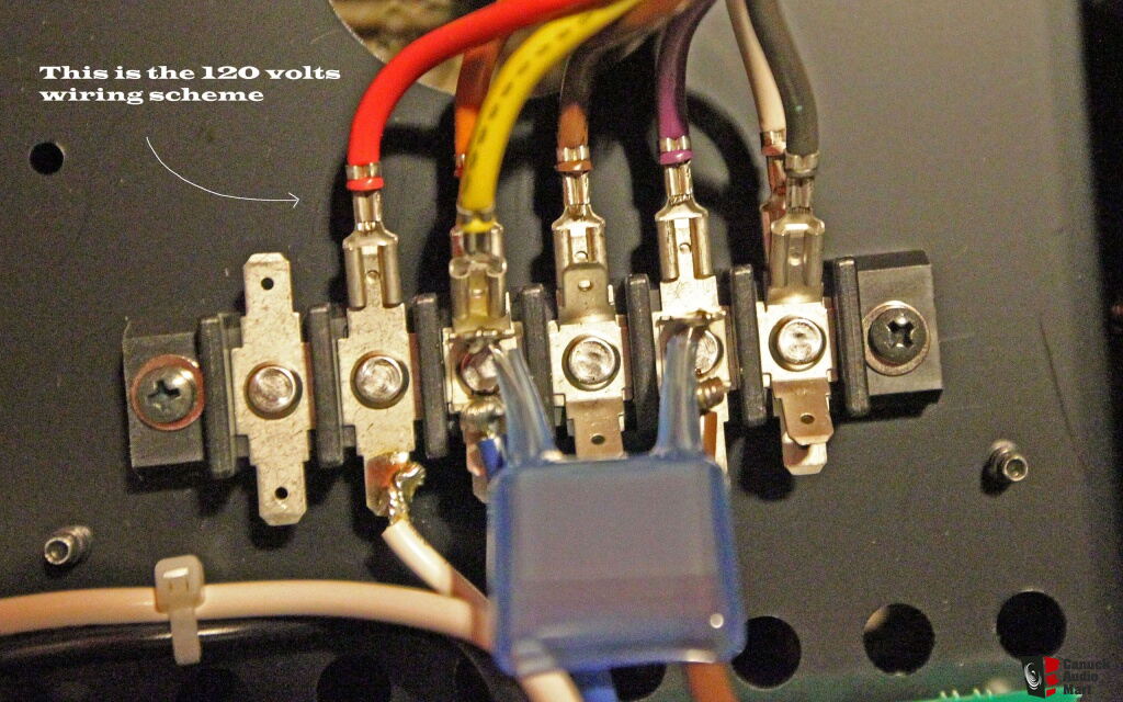
To convert the voltage from 100V to 120V, Move K3 to K5 and K4 to K6 position. Voltage conversion on E-600, E-650 and E-800 basically similar, first row of connections for 100V, second row for 120V and third row for 220/240V. For 100V and 120V mains, soft start resistors jumpers and fuse value remain the same. For 220/240V mains,disconnect jumper J1 and J3, install jumper wire on J2, change fuse accordingly. Accuphase design those built in power transformer for worldwide voltage, I don't think voltage conversion will affect sound quality. I hope I've answered your questions. |
@imhififan I really appreciate your sharing! This doesn't only help me but also those who have the same need in the future. Your answers address more than what I have asked! I have another question though, after desoldering K3 to K5, do I need to fill the empty holes in K3 and K5 with lead or they are ok to be empty? |
@imhififan I'm sorry for my typo, please ignore my previous questions. What I meant is: after desoldering K3 to K5, K4 to K6, do I need to fill the empty holes in K3 and K4 with lead or they are ok to be empty? |
@imhififan Many thanks!!! |
HIi @imhififan, you are a specialist as I understood:-) I want to switch my Dp900 & DC901 from 100v to 230v. Any idea if thats already discussed here in an other post? Or do you have an explanation already? In the older models it was much easier to do as it was described more or less in the device itself... Thanks in advance. |
Thanks! I'm just a HiFi hobbyist, Not a specialist at all🙂! Sorry I don't have any experience for voltage conversion of Dp900 or DC901. However, some Accuphase CD player utilize low power transformer with jumper setting, J1 for 100V, J2 for 120V and J3 for 220-240V, IIRC. If you can post a picture of the power board, perhaps we can figure out how to convert the voltage.
|
Hi @imhififan
hope it works with the pics: (link Icloud: https://www.icloud.com/iclouddrive/04bYXYU4boecaHce1E39q0HMA#Voltage) (link dropbox: ) My guessing: DP900: just change the two black wires with the two brown wires. DC901: As you said only change the jumper from J1 to J3 What do you think man:-) I have manual of the DP800/DC801 looks bit similar.
|
Good job! @systemroot👍, thanks for sharing! BTW, have you figured out what J4, J5 and J6 for?
|
@imhififan good question with J4, J5 and J6. I recognized you have mention something similar for the E600 above in context of soft start resistor settings. Any idea if I have to change these jumpers, too?
I think it makes sense to remove J5 and J6 but add J4. Then there is the maximimum resitor value set. I have manual of ps510 and there is also a kind of soft start circuit like this. |
| Post removed |
Hello @imhififan , thanks for your support of audio hobbyist! I used your instructions and switched the E-650 to 220-240 volts: I moved the connectors to the third row (K7, K8), disconnected the jumpers J1 and J3, installed the jumper on J2. When the amplifier is turned on through an incandescent lamp, the amplifier indicators do not light up. It should be? Watch the video:
|
@imhififan Incandescent lamp power 100 watts |
Thanks for the photos. I think the brown and blue cables are "live and neutral" come from the AC mains IEC socket, the small transformer is connected to it via a resettable fuse (F1), and the K4 is connected to the front panel power switch. When the front panel power switch engaged, RELAY1 energized and close the contacts to power the main transformer. I believe Accuphase made three versions of this board for 100V, 120V and 220/240V mains. If you want to convert to different mains voltage, a new board or install a small transformer with correct primary winding for the applied voltage is needed.
|
Thanks for the analysis, do you know what kind of miniature transformer is it? If i turn it on with higher voltage, will it burn? or the fuse will gone. or i just simply not able to turn on? what is see the red wire kind of link (by pass) from this board and go over to the next board which allow for the main transformer to have the voltage change. |
i remove the board out. Here what i understand, K2 input (brown) will switch to K1 (red) after relay turn on once power button press in and direct the current to sec board . Relay is 18VDC power by transformer (from K2) thru smd Z622. Im not sure what is z622? , i assume its rectifier to supply 18VDC to relay. or any double voltage will damage the z622?
|
Sorry, I don’t know what kind of miniature transformer is it. Measure the size, lead spacing and the output voltage and see if you can find a replacement for 230V.
The fuse (F1) will trip open circuit if connected to higher voltage, it will reset itself when that voltage removed. So it’s unable to turn on at all!
You can remove F1 ( just to be safe) and bypass the RELAY1’s contacts to allow the main transformer to have voltage change. However, the front power switch will be bypassed as well! You also need to check where is K3 connected to and see if it can work without power supply to this board.
I believe D3 (Z622) is a full bridge rectifier. BTW, perhaps you can try remove F1 and add a small transformer with 120V primary in series to the existing transformer primary winding to make it work for 220V mains.
|
I think the fuse is non reset-able and able to withstand till 300v. here the model i find Littelfuse 36911000000 369 T1A 300V Fuse micro fuse Time-Lag Radial Lead Square Fuse. The funny part is i was not able to measure any resistance after the fuse, meaning the 2 legs of the transformer, i suppose it have few milli ohms. |