@quanghuy147
To convert the voltage from 100V to 120V, Move K3 to K5 and K4 to K6 position.
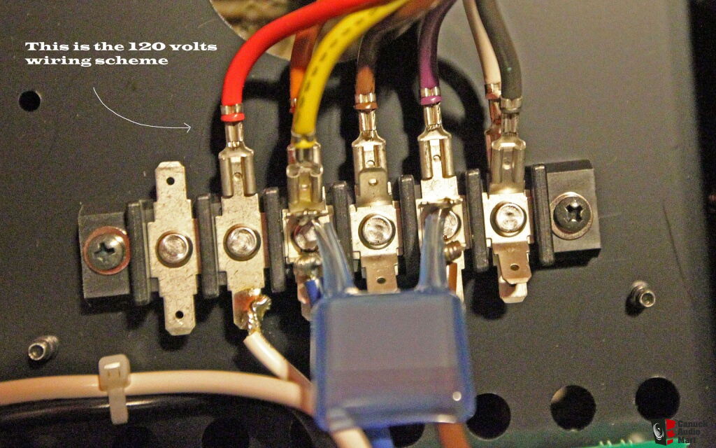
Voltage conversion on E-600, E-650 and E-800 basically similar, first row of connections for 100V, second row for 120V and third row for 220/240V.
For 100V and 120V mains, soft start resistors jumpers and fuse value remain the same.
For 220/240V mains,disconnect jumper J1 and J3, install jumper wire on J2, change fuse accordingly.
Accuphase design those built in power transformer for worldwide voltage, I don't think voltage conversion will affect sound quality.
I hope I've answered your questions.
|
Yes, Fill the empty holes in K3 and K4, it will increase the mechanical strength of the PCB especially holes with through hole plating.
Hope this helps
|
If you can post a picture of the power selection board, maybe I can provide some help on the voltage conversion.
BTW, have you completed the A-48 conversion?
|
Desolder K3, K4 and solder it to K5, K6 position will convert input voltage from 100V to 120V.
Again, I recommend use a dim bulb tester for first time power up the amplifier after voltage conversion.
Hope this helps.
|
Glad
it
done successfully
... thanks for letting us know.
|
@systemroot
Thanks! I'm just a HiFi hobbyist, Not a specialist at all🙂!
Sorry I don't have any experience for voltage conversion of Dp900 or DC901. However, some Accuphase CD player utilize low power transformer with jumper setting, J1 for 100V, J2 for 120V and J3 for 220-240V, IIRC.
If you can post a picture of the power board, perhaps we can figure out how to convert the voltage.
|
works as expected:-)
Good job! @systemroot👍, thanks for sharing!
BTW, have you figured out what J4, J5 and J6 for?


|
I think it makes sense to remove J5 and J6 but add J4.
Yes, you got that right.
This works as well for the soft start circuit:-)
Congrats! Thanks for letting us know.
|
|
|
|
@eugene81
Congrats! Thanks for posting the photos.
|
|
When the amplifier is turned on through an incandescent lamp, the amplifier indicators do not light up. It should be?
What’s the wattage of the incandescent lamp?
|
Two possibilities:
1. The incandescent light bulb too low in wattage
2. Short circuit
@zeptul
According to the specs E-650 draws 168 watts @ idle. Please try a 250 or 300 watts bulb. If that does not light up the amplifier, you need to check the soldering of all connectors.
|
Victor,
I'm glad you figured it out.
👌✌👍
|
@jsch9876
Hi Jason, E-650 and E-800 are class A integrated amplifier, the E-380, E-4000 and E-5000 are class AB integrated.
Sorry I have no experience of E-5000 voltage conversion, I think its power board is different from E-650 and E-800. Maybe it's similar to E-370, E-470 or E-480 which is utilize jumpers.
|
@leecc73
It look like a stand-by board, what is the amplifier model number? Can you post a photo of the back of this PCB? Where those brown, blue and red cable came from?
|
@leecc73
Thanks for the photos.
I think the brown and blue cables are "live and neutral" come from the AC mains IEC socket, the small transformer is connected to it via a resettable fuse (F1), and the K4 is connected to the front panel power switch.
When the front panel power switch engaged, RELAY1 energized and close the contacts to power the main transformer.
I believe Accuphase made three versions of this board for 100V, 120V and 220/240V mains. If you want to convert to different mains voltage, a new board or install a small transformer with correct primary winding for the applied voltage is needed.
|
Sorry, I don’t know what kind of miniature transformer is it. Measure the size, lead spacing and the output voltage and see if you can find a replacement for 230V.
If i turn it on with higher voltage, will it burn? or the fuse will gone.
or i just simply not able to turn on?
The fuse (F1) will trip open circuit if connected to higher voltage, it will reset itself when that voltage removed. So it’s unable to turn on at all!
what is see the red wire kind of link (by pass) from this board and go over to the next board which allow for the main transformer to have the voltage change.
You can remove F1 ( just to be safe) and bypass the RELAY1’s contacts to allow the main transformer to have voltage change. However, the front power switch will be bypassed as well! You also need to check where is K3 connected to and see if it can work without power supply to this board.
Relay is 18VDC power by transformer (from K2) thru smd Z622.
Im not sure what is z622? , i assume its rectifier to supply 18VDC to relay.
I believe D3 (Z622) is a full bridge rectifier.
BTW, perhaps you can try remove F1 and add a small transformer with 120V primary in series to the existing transformer primary winding to make it work for 220V mains.
|
@leecc73
I think the fuse is non reset-able and able to withstand till 300v. here the model i find
Littelfuse 36911000000 369 T1A 300V Fuse micro fuse Time-Lag Radial Lead Square Fuse.
Thanks for the info, in that case, the fuse will blow if exceed its power rating. However, IMO, 1A fuse is too high and unable to protect this transformer.
The funny part is i was not able to measure any resistance after the fuse, meaning the 2 legs of the transformer, i suppose it have few milli ohms.
That’s weird! unless the primary winding is shorted (due to over voltage?), it should has more than 10 of ohms resistance for such a small transformer. I got reading of 24ohms on primary winding of a 24VA transformer and 36ohms on a 12VA transformer. You should measure it with the blue and brown cable disconnected to get accurate reading.
|
|
@dbxdx5
Yes, switch the voltage from 100V to 120V, leave jumpers J1 and J3 unchanged.
|
@dbxdx5
While it is not necessary to bias the power amplifier after voltage conversion, I thought it would be a good idea to record the rail and bias voltages before conversion for future reference.
|
In addition to the above changes, if there is an auxiliary transformer, it will also need to be changed from a 100vV model to a 220/240V model.
|
@susurin
Yes, K3 to K7 and K4 to K8 will convert 100V to 220/240V.
Remove J1 and J3 and install a jumper to J2, which will convert the soft-start resistor array from 100/120V to 220/240V.
|