Wiring 2 outlets to 2 dedicated 20 amp circuits with a single 10/3 electrical wire.


Here's an idea (and it is code compliant), using one 10/3 romex electrical wire (three insulated conductors, and a bare ground wire - 10 gauge), you can wire two outlets to a double pole breaker (and yes the legs would not be the same, which on a quiet electrical system is not a big deal).
 

In this situation, 2 hot wires from the outlets would be wired directly to each of the circuit breakers, the neutral would be bridged between the two outlets and then connected to the appropriate spot on the panel, and the grounds for each outlet would be attached to the single ground wire that goes back to the panel.  This would all appear within a quad outlet wall panel (ie. Two 20 amp outlets side-by-side)

For a long 70 foot run this seems prudent thing to do, less costly and kosher.

emergingsoul

Showing 14 responses by jea48

@emergingsoul ,

Don’t do it! Are you trying to save money on the wiring and installation? Not a good place to cut costs.


I can’t believe the number of posts I have read lately where audiophiles have used, or are considering using, this type of wiring method to feed their audio equipment. The reason for a multiwire branch circuit is save money. Period!

There may be 10s of thousands of dollars in audio equipment involved and the user chooses to save a few bucks by using this type of branch circuit wiring. Sorry, I just don’t get it...

Each Hot, (Ungrounded Conductor), must be connected to breakers fed from both Lines, legs, in the same electrical panel. Therein 240V between Lines, legs. (The 2 Hot conductors cannot be connected to breakers on the same Line, leg.)

Both breakers must be tied together with an Approved Listed tie to simultaneously open both breaker with one handle action. (A 2 pole breaker meets this NEC requirement. (New NEC 2008 requirement) .

Here is a YouTube video on multiwire branch circuits. LOL, sometime Mike Holt comes off a little like an air head but he is far from that. Holt is one of the members of NEC Code Making Panel. He’s one of many people that helps write the NEC...


@tump350 Said:

One circuit for the digital front end, the other circuit for the preamp and monoblocs.

Would you believe all the digital hash going back out on the power AC Lines from the digital equipment is dumped onto the power transformers primary windings of the preamp and monoblocks? Only the unbalanced load(s) current of Line 1, (L1), to shared neutral, and Line 2, (L2), to shared neutral load(s) current return on the 3 wire multiwire branch circuit neutral conductor to the neutral bar in the electrical panel. All of the digital 120V Line to neutral loads (jointed connection in the outlet box) is in series with the Analog 120V Line to neutral loads. The balanced loads are in series with one another and fed by 240V...


Jea48

What the heck are you talking about?

@emergingsoul ,

Probably the biggest reason for installing more than one Dedicated Branch Circuit is to decouple the power supplies of audio equipment from one another. Example digital source(s) equipment from analog equipment.

A true dedicated branch circuit has a dedicated Hot conductor, neutral conductor, and equipment grounding conductor. A true dedicated branch circuit does not share a raceway, (conduit), or cable with other branch circuits.

Your thread title:

Wiring 2 outlets to 2 dedicated 20 amp circuits with a single 10/3 electrical wire.

What you are suggesting using is called a multiwire branch circuit. It has two 120V separate circuits, (Not Two Dedicated Circuits), that share a common neutral conductor. Bad for audio equipment, imo... It’s actually worse than installing two 120V dedicated circuits and terminating on breakers from Both Line 1, leg, and Line 2, leg instead of installing both on the same Line, leg.

A multiwire branch circuit actually couples the power supply’s of audio equipment of one circuit to equipment on the other circuit.

Here is another video for you to watch. Imagine the output of the split phase transformer being an electrical panel. Imagine the voltage is 120/240V. (Two Hot conductors and one shared neutral conductor). The wires leaving the transformer secondary is a multiwire branch circuit. The single light bulb load represents digital source loads. The other bulb with the parallel resistor load represents a preamp and power amp.


Only the unbalanced load current of the two hot conductors return on the shared neutral conductor to the source. The balanced load is in series with one another and is fed by 240V.

FWIW, multiwire branch circuits are commonly used in commercial and industrial facilities. Why? It saves material and labor costs. It’s even used, somewhat, in residential dwellings. It has its place of use. I personally would not use a multiwire branch circuit to feed my audio equipment though. YMMV.


Here is another video I found doing a quick Goggle search. The guy does a good job of explaining how a multiwire branch circuit works. He does have a few problems in his explanations and terminology used at times though. Like his use of saying 220V at times instead of 240V. Overall though he gets his message across.


Note..., only the unbalanced load current returns on the common neutral conductor to the source. The balanced load current is in series and is fed by 240V. Voltage drop across each load will still measure 120V nominal. (As long as the common neutral conductor is not broken)...


EDIT:

  (  jea48 said:     

A multiwire branch circuit is merely an extension of the split phase winding of the utility power transformer.

Replace the word merely  with the word basically.

A multiwire branch circuit is basically an extension of the split phase winding of the utility power transformer.

.

@emergingsoul said:

Yes I know both new circuits or an alternating legs, and that could be a real weakness.


But if all the legs where I live are generally quiet then I don’t see the problem on this point.

Got Digital Front End Equipment? The hash it puts back out on the mains ain’t quiet.

Got any SMPS (Switched Mode Power Supply)s? The harmonics they put back out on the mains ain’t quiet.

Using a multiwire branch circuit will dump that crap on the doorstep of the power transformer’s primary winding of the analog equipment. You want noise, that’s a good way to introduce it into your analog equipment.

The other issue, there is a common neutral wire representing a return connection to the panel, but it’s not the incoming voltage wire.

It takes two to tangle.

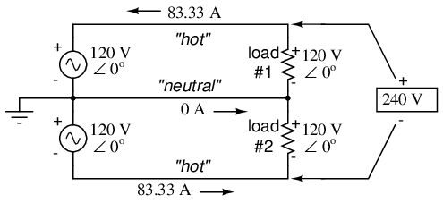
It takes both lines to feed a 120V potential to a load for current to travel in the circuit. Current travels from the source through the load and returns to the source. The neutral conductor is a current carrying conductor. The same as a hot Line conductor is a current carrying conductor.

Are you saying noise could bleed back to the audio equipment from the neutral?

NO, I am not.

Here is the circuit using a multiwire branch circuit... I hope you can follow it. Draw a one line diagram on a piece piece of paper showing flow of the current through the series circuit.

At the panel you have a Hot L1 bus and a Hot L2 bus.

L1 breaker hot conductor to >>>

digital equipment power transformer primary winding, (OR, SMPS), out to >>>

neutral conductor to junction with shared branch circuit neutral conductor. Neutral conductor from shared neutral junction to >>>

amp primary winding through winding out to >>>

Hot L2 conductor back to the electrical panel breaker on L2.

See it ain’t neutral current carrying the "Noise" created by the digital equipment. It’s the L1 & L2 balanced load current that travels through the AC line side power supply of the digital equipment >>> through the line side power supply of the analog equipment out >>> on L2 back >>> to the electrical panel.

By design the multiwire branch circuit feeds the balanced load current that is fed from Hot L1 conductor >>> (digital equip) >>> in series with >>> (analog equip) >>> Hot L2 back to the electrical panel .

Keep in mind this is a 70 foot run for a romex wire.

Yeah, I got two 10/2 with grd Romex runs 70ft each. Installed them using best practices methods. One dedicated circuit is for digital equipment, the other for analog equipment.

No ground loop hum. No noise. System is dead quiet with ear against speaker grill.

Preamp and power amp are tubes. Dead quiet...


I’m trying to keep this conversation understandable because I think people get lost when it’s not dumbed down for non-engineering finance side people

Trust me I’ve tried my best to explain how a multiwire branch circuit works in layman terms. Did you watch the videos I supplied. Did you understand them?

.

@bikeboy52 

Bad Idea...


A true dedicated branch circuit has a dedicated, Hot conductor, neutral conductor, and equipment grounding conductor. A true dedicated branch circuit does not share a raceway, (conduit), or cable with other branch circuits.

An Overview of Audio System Grounding and Interfacing

Se page 16. Read pages 31 thru 37.


/   /   /   /


A true dedicated branch circuit does not share a raceway, (conduit), or cable with other branch circuits.

Current carrying conductors from one branch circuit can induce a voltage on the conductors of the other circuit.  Therein if there is noise on one circuit it could be induced onto the other circuit.

.

@emergingsoul said:

Are you saying that the neutral sharing back to the panel is a problem?

It’s more than that. It’s the way a multiwire branch circuit works.

I have been trying to find this Web Link for the last couple of days. It was in my Bookmarks but I must of accidentally deleted over the years. Anyway try to follow what is said. Stop when you reach "Three Phase Power Systems" ...

A multiwire branch circuit is merely an extension of the split phase winding of the utility power transformer.

https://www.ibiblio.org/kuphaldt/electricCircuits/AC/AC_10.html


Truth be known, I specifically directed the electrician to create two dedicated lines on the same leg, and then he pulled this crap and I had to live with it.

I believe it... Some electricians just don’t listen.


I couldn’t get a second dedicated in the elsewhere room because I ran out of room on the panel.

You could install a Tandem breaker.

Tandem Breakers - Circuit Breakers - The Home Depot

.


@emergingsoul said:

The issue is trying to clarify why noise somehow is affecting the outlet in a manner that impacts performance of a system.

Maybe why noise from one circuit is affecting audio equipment connected to the other circuit of the multiwire branch circuit.

Lets try this again.

Just for an example.

Say on circuit Hot L1 conductor (coming from the electrical panel) you have a total connected 120V load of digital equipment of 2 amps.

Say on Hot L2 conductor (coming from the electrical panel) you have a 120V analog integrated amplifier load of 2 amps.

L1 = 2 amps.

L2 = 2 amps.

Load is Balanced on both L1 and L2.

Because of the way a multiwire branch circuit works Zero amps will return on the shared neutral conductor to the source).

So where is the circuit for the current (amps) to flow back to the panel, (source)?

The two connected loads are in series with one another. The shared neutral conductor from the panel is not involved.

One line diagram.

L1 conductor from panel >>> digital load >>> in series with >>> integrated amp >>> L2 conductor from panel.

The two series loads are being fed by 240V. (There is still a voltage drop across each load of 120V... 120V + 120V = 240V.)

So hopefully you can see the noise from the digital equipment, (if present), will be transferred to the primary winding of the power transformer in the integrated amp in the current as it passes through the primary winding back to the source on L2 conductor.


/ / / /


Note:

The source is actually the 120/240V split phase secondary winding of the Utility Power Company’s step down transformer.

.

@emergingsoul said:

You say that, Zero amps will return on the shared neutral conductor to the source).

Well it’s a fact... That is how a center tapped single phase 120/240 secondary winding of a step down transformer works.

Watch this video again. Make note the guy has the switch opened on the shared neutral conductor and the two light bulbs stay lit. The two light bulbs are in series with one another. At one point in the video he removes one of the bulbs, (breaks the series circuit), the other light bulb goes out. He reinstalls, (completes the circuit), and both bulbs are lit again.


@emergingsoul ,

Look at the first schematic diagram below.

Note: Load 1 and load 2 are identical. The loads are Balanced.

Note: The shared "neutral". 0 A (The shared neutral is not involved).

Load 1 and load 2 are in series with one another and are fed by 240V


Addition of neutral conductor allows loads to be individually driven.


Instead of a single 240 volt power supply, we use two 120 volt supplies (in phase with each other!) in series to produce 240 volts, then run a third wire to the connection point between the loads to handle the eventuality of one load opening. This is called a split-phase power system. Three smaller wires are still cheaper than the two wires needed with the simple parallel design, so we’re still ahead on efficiency. The astute observer will note that the neutral wire only has to carry the difference of current between the two loads back to the source. In the above case, with perfectly “balanced” loads consuming equal amounts of power, the neutral wire carries zero current.

Notice how the neutral wire is connected to earth ground at the power supply end. This is a common feature in power systems containing “neutral” wires, since grounding the neutral wire ensures the least possible voltage at any given time between any “hot” wire and earth ground.

An essential component to a split-phase power system is the dual AC voltage source. Fortunately, designing and building one is not difficult. Since most AC systems receive their power from a step-down transformer anyway (stepping voltage down from high distribution levels to a user-level voltage like 120 or 240), that transformer can be built with a center-tapped secondary winding: (Figure below)


American 120/240 Vac power is derived from a center tapped utility transformer.

https://www.ibiblio.org/kuphaldt/electricCircuits/AC/AC_10.html

/ / /

Note: See the two 120V rectangles?

Connect a 2A digital load across one and a 2A analog load across the other. 0 amps will return on the shared neutral. the two loads are in series and are fed by 240V


@emergingsoul

I’m beginning to think you are just pulling my chain here...🤔

Where does the power that feeds your house come from?

A Utility Power Company?... Somewhere outside your House there is a step down power transformer that feeds power to the electrical service of your house...

Without a Single Phase 120/240V SPLIT PHASE power system there would be no 3 wire single phase multiwire branch circuit... Can’t have a 3 wire multiwire branch circuit without a split phase power system. The Utility Power Company’s step down power transformer’s center tapped 240V secondary winding is what creates the 120/240 split phase power system.


/ / / /


You asked Why?

Not sure why this would be happening.


jea48,

You say that, Zero amps will return on the shared neutral conductor to the source).

Not sure why this would be happening. And then from this point on in your response above I sort of lose an understanding of what you’re saying.

But I’m really trying to follow. And I think for many it would be nice to know the rationale here as well, as this is a very profound issue.


Remember This Post:

Jea48 said:   (12-21-2022 at 08:46am)

A multiwire branch circuit is basically an extension of the split phase winding of the utility power transformer.


.


@emergingsoul said:

My question focused on noise which is the issue. And if there’s no noise coming from the neutral, and the ground, assuming these are connected correctly at the panel, and the panel secures the ground via a stake in the dirt, what is the problem??

I have answered your question(s) several times throughout this thread. In about every variation I can think of that gives the same answer to your question(s).

You keep talking about noise on the neutral and the ground conductor. I don’t know where you are getting that from... The problem with audio equipment fed from a MWBC, (Multi Wire Branch Circuit), is not caused from the shared neutral or EGC, (Equipment Grounding Conductor). It caused by the Balanced L1 120V loads being connected in series with the L2 120V loads. You couldn’t find a better way to couple the 120V power supplies of your audio equipment together than using a MWBC to feed them.


JMHO, you would probably be better off just using one of the circuits, (turn the other one off at the panel), and power all your audio equipment just off the one. Pick up a good quality power strip for more outlets if needed.


As I have said several times in this thread the 120V L1 and 120V L2 Balanced loads (current) are in series with one another. The Noise you speak of comes from the power supplies of digital equipment, as well as any cheap made SMPS. There is your noise... The use of a MWBC dumps it right onto the primary winding(s) of the power supplies of the analog equipment. (Preamp, Power Amp, ect)

Maybe you don’t have any digital equipment or equipment with SMPS. Then there is a good chance a MWBC works fine for you. Or if you do have digital front equipment and SMPS maybe the designers/manufacturer spent the extra money to add filtering to prevent digital hash from going back out onto the mains. And maybe the designer/manufacturer of SMPS(s) spent the extra money on the build quality of the SMPS(s) and filtering to prevent bad harmonics from going back out on the mains.

.

FWIW, If your audio system sounds good to you that’s all that maters.

FWIW, you could have a new dedicated circuit installed, (10/2 Romex), and then have the electrician change the MWBC to just a two wire Hot & neurtral + grd dedicated branch circuit. Make sure the electrician feeds the two dedicated branch circuits from the same Line, Leg. Both from L1 or both from L2...

Any Electrician worth his salt can rework the panel circuits to free up two breakers that are both on the same Line, Leg.

I strongly suggest you don’t use the last electrician the installed the MWBC...


@emergingsoul said:

And because of the push pull action of the circuit because it’s on alternate phases the neutral wire has no current.

Not exactly...

Only the unbalanced 120V loads of L1 & L2 returns on the neutral conductor to the source. The balanced 120V loads of L1 & L2 are in series with one another and fed by 240V.

Example:

Say L1 120V load is 2 amps and L2 120V load is 6 amps. 2 amps is the balanced load. The difference of 6A minus 2A = 4A. 4A is the unbalanced load and returns on the neutral conductor to the source.

The L1 120V 2A load represents digital equipment.

The L2 120V 6A load represents a preamp and power amp.

.

@rbertalotto said:

So, are you saying both circuits should be run from the same leg on the panel rather than one circuit on each leg?

I plan on running two 12/2 - 20amp circuits, 24’ and terminate in two quad outlet boxes......Yes/OK?

And, if I’m running two 12/2, should the run side by side, be spaced a certain distance apart


Yes to all the above.

A true dedicated branch circuit does not share a raceway, (conduit), or cable with other branch circuits.

Current carrying conductors from one branch circuit can induce a voltage onto the conductors of other branch circuits. Therein if there is noise on one circuit it could be induced, transferred, onto other circuit(s). Same reasoning is used for keeping parallel running Romex dedicated branch circuits spaced apart, away, from one another. That includes keeping audio dedicated branch circuits spaced away from existing parallel running branch circuits. Especially Lighting branch circuit using dimmers and or LED lights...


It has been an accepted norm for years multiple audio equipment dedicated circuits should be fed from breakers fed from the same Line, leg.


"Less than 300 microamps of ground loop current can cause hum as it flows in an unbalanced audio interconnect cable. However, harmonics of 60Hz that are generated from lighting dimmers or switch-mode power supplies sound like Buzzz mixed with a bit of Hummm and are more easily coupled by even smaller currents. Harmonics can add together when equipment is powered from different phases, so clearly there is an advantage to specifying same-phase electrical service to power the electronics systems in most cases....

Any leakage currents on the safety ground wires of split single phase load circuits fed by different phase legs will add together due to the 240V potential difference....

Power conditioners do not solve any of these common problems: Cross phase coupling (doubles hums & buzzes) .... What actually does solve them: Same phase power.

http://www.exactpower.com/elite/assets/pdfs/theTRUTH.pdf

Also for reasons stated in this thread.

/ / /


FWIW, my guess would be most audiophiles have more than one dedicated branch circuit installed to help decouple the power supplies of equipment from one another. Especially digital equipment from analog equipment. Also SMPS from linear power supply analog equipment. Add up all the equipment FLA, VA, wattage, in most cases the combined total load of all the equipment is less that 8 to 10 amps, 960W to 1200W. 80% of a 20 amp circuit is 16 amps, 1920 watts.


As for this:

or be twisted over the 24’ length?

I would not deliberately twist Romex. Doing so will change the lay, geometry, of the way the bare equipment ground wire is placed between the Hot and neutral current carrying conductors. Altering the placement of the bare ground wire between the Hot and neutral current carrying conductors may cause a greater chance of an induced voltage onto the ground wire causing 60Hz ground loop hum and or 60Hz buzz.

When you read where it is recommended to twist conductors together that is for single Hot and neutral current carrying conductors that will be installed in a raceway, conduit. The insulated equipment ground conductor is installed straight along side the twisted pair.

I would recommend 10/2 MC, (Metal Clad) aluminum armored cable over NM sheathed Cable,(Romex). The Hot, Neutral, and insulated green equipment ground, conductors are tightly twisted in a spiral the entire length of the MC cable. The aluminum armor tightly holds the twist of the conductors together. The aluminum armor also helps reject RFI.

Integrating Electronic Equipment and Power ... - Ground One

Read pages 11,12, 13

/ / / /


A Licensed Electrician is recommended for the installation of MC cable. It’s not for a layman to install. The AL armor must be properly cut to expose the insulated conductors for make up to the box connector. Proper methods must be followed so as to not damage the insulation covering the conductors when removing the AL armor. A red UL approved pvc insulator must also be properly inserted/installed between the AL armor and conductors. Hire an Electrician...

.