Pindac, I should mention when a private party flies into the USA, buys a product here, and returns with it to the UK or EU, that is technically a "grey market" sale. There is usually no legal problem with the new toy, assuming the local duties and VAT are paid ... but usually it is not legal to re-sell in that country. EU countries take a dim view of grey market sales ... while I have no idea how aggressive UK enforcement is. (In the US, the Federal government doesn’t care about grey market sales, but overseas warranties will not be honored by repair shops.)
And warranty support ceases once it is taken out of the North American market. The primary purpose of an overseas servicing center is to provide continuing warranty support, at a quality standard that matches the original manufacturing quality, with the same parts, service manuals, employee training, etc.
(A "black market" sale, of course, is something that is completely illegal to import into the host country, like an AR-15 into the UK, or something like that. Many laws are broken and arrest warrants are issued. "Grey market" means the product has not been tested by the relevant safety agencies, and is not certified for sale in that country. The most common outcome is that it is seized by Customs and is not returned.)
|
My father was a US diplomat and head of the Economic Section of the U.S. Consulate in Hong Kong, and held a similar position at the US Consulate in Osaka, Japan. His primary function was smoothing the way for US business overseas, and making sure they didn’t break local law and get arrested (not joking about this). It’s the job of the nearest US Consulate (or Embassy) to fish Americans out of jail when they unwittingly break local law. Most Americans are unaware they are subject to local law when they travel, with the only exception being US diplomats and members of the Armed Forces. They have separate passports ... I myself held a diplomatic passport until I was 18 and returned to the States.
Hong Kong was very unusual being a Free Port, with zero import duty on goods from anywhere in the world. Back then in the Sixties, the only prohibited goods were guns (of any kind), illegal drugs, and gold. Anything else got a perfunctory inspection and went into Hong Kong warehouses for re-shipment to anywhere else in the world.
Thanks to decades of trade agreements with most countries in the world, the USA is very nearly a duty-free zone, with only the lightest restrictions into our markets. The Chinese government greases the wheels even more by providing free shipping for Chinese manufacturers into the US market (yes, really). But shipping back to China is definitely not free, as anyone with a defective Chinese product will discover. That’s why you should always confirm there is a functioning, and fully staffed, repair agency in North America when buying a Chinese product.
Americans cheerfully assume the rest of the world is this way ... LOL, ha ha, no, not at all. Not even slightly. There’s free trade within the EU, but there’s a maze of mind-numbingly complex safety and technical regulations to gain entry into that market. The big Japanese firms have the resources, but they have full-time staffs doing just that. The EU is a beautiful place and delightful to live in, but in terms of trade, it is a walled garden. Entry is possible but the requirements are daunting ... and are designed that way.
Gaining entry into Japan is nearly impossible. It can take decades. Even Wal-Mart has barely cracked it, and think of the massive resources they can bring to bear. Tourists are always welcome, but good luck immigrating to Japan, or cracking the local market.
Every country in the world is different, with different sets of legal hoops to jump through. Some, like Japan, are essentially closed. China is nearly closed, with complex and difficult currency restrictions. Hong Kong and the USA are very much the exceptions, not the norm.
The USA took the political decision after World War II that it wanted to sponsor worldwide free trade, backed up and protected by the US Navy. (The US Navy has 13 nuclear-powered Carrier Battle Groups. Any other country has just one carrier, and they are not nuclear-powered. Think about that for a while.) The US wanted to dissolve the squabbling European empires that had caused two World Wars, and had the economic muscle to do so. This is still US policy.
|
Japan is interesting. Unlike the USA, it looks outward to the world (Americans by and large don’t know or care), but any kind of immigration is nearly impossible. Visit, yes, but don’t stay. This is a demographic problem with a rapidly declining population and no effective guest-worker program.
What makes the USA unique is that it only imports 12% of its economy, less than nearly any other nation, and half of that are imports from Mexico and Canada, which are effectively domestic markets. Get rid of those two and it is 6% or less.
It is self-sufficient in energy for the foreseeable future, and for the history of the country has always exported food to the rest of the world. The USA has never had a food famine in its entire history, which is unique as far as I know. So Americans are pretty insular compared to most other nations, and only the larger companies have any awareness of the ins and outs of selling to non-North American markets.
In the rest of the world, it is Export Or Die, and governments are tightly focused on this, every day. Because essential inputs, like food or oil, come from elsewhere, and are critical to the survival of the population. In the USA, there’s always more. It’s always been that way. Our economic problems are self-inflicted. The idea of HAVING to export is very foreign to Americans, but is no joke in the UK, the EU, China, Japan, and much of the rest of the world.
|
About 12,000 naturalized immigrants a year, it turns out, out of a population of 123 million. Not enough to offset a population loss of about a half-million to a million a year.
Returning to the original question, Asian companies are a lot more export-oriented than US companies. They have far more experience exporting to North America and the EU, and are expert in making "localized" versions.
Japan is also interesting because half the country is 50 Hz (Tokyo), and the other half (Kobe/Osaka) is 60 Hz. Asynchronous 50/60 Hz Grids. In a sense, even the internal market is an export market, since there are two power frequencies.
|
I saw Kurobe Dam while it was under construction by Kansai Electric. The underground power station, deep under the mountain, is like sometime out of a Bond movie set. Two of the generators were running while the third was suspended from a crane. The fourth was an immense concrete pit.
|
As Whitestix mentions above, the Japanese have a "purist" esthetic that applies to audio. But it goes much deeper than that. The CEOs and top engineers of Japanese, Korean, Taiwanese, or Chinese companies are not going to be impressed by the latest mass-produced gadget. Hardly. That’s the stuff they make every day, and they make it to very high reliability standards.
What they appreciate is artisan audio made to the highest standards, by artisans of superb taste. Not 1" thick anodized-aluminum front panels with a giant meter in the middle. That only impresses naive Americans who have never worked in manufacturing,
What impresses them is genuine American aerospace-grade quality, if circuit boards are involved, or artisan hand-tuned point-to-point circuitry. And they are not impressed by magazine reviewers, since they have an insider’s view of the publishing industry, and are very aware of how American marketing works.
|
I was only 11 at the time, but I was dazzled by the private tour of Kurobe Dam. It’s size of Hoover Dam and freaking huge. The dam was nearly finished when we visited as guests of Kansai Electric, and we took this strange little Elves railway deep, deep into the mountain. We got out of our mini-train carriage into a brightly lit station with gleaming tiles, and directly opening into a modernist office area, with desks and office furniture.
Rather than office windows looking outside, there was a massive expanse of glass overlooking the turbine hall, from three stories up. I assume the control room was in the floor underneath us ... didn’t get to see that, but we did go to the main turbine hall. Two were up and running, the third Hitachi-made unit was on a crane, and there was a vast and deep concrete pit for #4, yet to arrive. All new and the walls all done in gleaming white tile, not bare concrete. Basically, an office and power station deep in a mountain, with a very quiet thrum as enormous quantities of water flowed through the penstocks into the turbines. You could just barely feel it.
We left by another route and saw the ultra high tension power lines coming out of the mountain, There was a faint glow around the wires from corona discharge and a sound like crickets from overhead.
Dad drew our attention, as we left on the micro train out of the very deep valley, that all this was being built 15 years after the most overwhelming defeat in history, with nearly every Japanese city in smoking ruins, and tens of millions on the verge of starvation. A scant 15 years later, a Japanese-made technological wonder that put Hoover Dam in the shade. It left quite an impression.
I have to give Dad credit. As Economic Attaché, he wangled some spectacular tours while we were overseas. Kurobe Dam. A Japanese steelworks at full blast. A visit to the 8-reactor carrier Enterprise. A visit to a factory assembling magnetic-core memory. An aerial tour of Hong Kong on a four-engine Super Constellation as the FAA aligned Kai Tak’s landing systems.
Although he was a diplomat with a Masters in Economics, he was a big fan of technology, the more spectacular, the better. If you want Big Tech, Asia’s the place.
|
Yeah, RoHS-approved solder might be a stumbling block, since it requires higher temperatures and a little different technique. We’ll cross that bridge when we get there. Our first goal is getting production under way in Salt Lake City, home of Spatial Audio.
Fortunately, both Salt Lake and Denver have a number of aerospace vendors that make various subassemblies for rockets and satellites.
|
Which is why medium to large scale companies have regional service centers, which combine repair, refurbishing, and overall product support in one center. It’s equivalent to a low-yield manufacturing center with a marketing wing (in the local language) attached.
They support local retailers, or have direct customer support, and offer the kind of services manufacturers do, just on a smaller scale. Somebody to answer the phone. A parts warehouse. Several techs to repair or upgrade the product. Somebody to manage the facility and make sure things actually get done, along with inventory and personnel management. In short, at least three to ten people working full-time, along with leased space in an industrial park. It’s equivalent to a small factory, with equivalent monthly overhead costs, too.
Once your company passes the threshold of about five to fifty million dollars a year in sales, yes, opening overseas centers in regional markets makes economic sense. You can afford to hire three to ten new workers on another continent, and train them and point them in the right direction. Opening a regional service center requires a pretty steep investment in time and money.
Otherwise, you are supporting the overseas customers by remote control, with very expensive shipments back and forth, and a certain percentage of those returned products severely damaged in shipment because the customer threw away the original packaging and improvised their own packaging.
|
I'm not sure what to tell potential overseas customers to do. Sure, after you hear all the market buzz and read the first reviews, you might be tempted to get on a plane, fly right to Salt Lake City in the state of Utah and buy yourself three good-sized boxes ... a matching Raven, and a pair of brand-new, state-of-the-art Blackbirds. Be the first person in London or Berlin to own the full set. How cool is that?
But ... if anything goes wrong, or you just want some hand-holding, or want to ask what our favorites cables are ... you're kind of on your own. You're not in the same time zone as we are. We don't know anything about the ins and outs of UK and European power supplies, nor what favorite NOS tubes are in your area. Sure, with time, we'll find European affiliates that are a good match. With time, in Asia as well.
|
|
We'll cross that bridge when we get to it. So far, we haven't ordered any multi-voltage power transformers. When we do, we'll dig into the applicable CE regulations ...
|
I should mention additional heating from 50 Hz working is a non-issue. The design of the power transformer, rectifiers, and regulators are extremely conservative and run very cool. Don has measured the thermals all around the chassis, and we have plenty of headroom everywhere. So no issues there.
|
I did most of those things for the Seattle trip. I hadn’t flown in more than a decade, and I knew it would be Hell on Earth if I didn’t tick all the boxes. So, in the months preceding, I applied for TSA Pre-Check, Instant Bag Check using the QR code on the phone, Early Boarding (for a fee), Lounge Access (lounge was closed), and Extra Seating Room (because I’m 6’ 1").
Most of it worked perfectly. TSA Pre-Check was fast and efficient. Instant Bag Check, likewise. Early Boarding, same. Extra Seating Room, yup, and pre-checked into a window seat both ways. Check. All perfect and worth every penny.
But ... the *&$@# concourse in Denver Airport was miles long, and there are several of them, connected only by a standing-room-only subway. And United changed the gate THREE times, sending a text to my phone just after I hiked all the way to the end of a concourse A, only to find no flight to Seattle after getting there. So then the flight is changed to the end of Concourse B (walking all the way back, taking the jammed subway, and walking all the way to the end of ANOTHER concourse), and then it got changed a THIRD time, right back to the end of Concourse A.
It must have been at least two miles, and there is nowhere to sit on this trek. Hey, airports are supposed to be ADA compliant, and I’m a tired old geezer about to fall over. So I ask a porter, can I get a ride in one of those ride-alongs I see whizzing by. Nope, you have to reserve a seat at least a day ahead with the airline you are flying on. No ride for you!
So ... the airport is grossly out of compliance with ADA unless you reserve at least a day ahead. Too bad if you are a single mom with an exhausted toddler, disabled with a crutch, or just plain old, like me, You get to walk, and walk, and walk, and if you fall over, well, tough. That’s your problem.
Oh yes, and I got Covid when I came home, almost certainly in the Denver or Seattle airports, which are both jammed each way. And then Karna got it 36 hours later, from me. Fortunately, Paxlovid dispatched it in a couple of days.
So I learned two things: wear an N95 mask in the airport, jetway, and airplane, until the airplane A/C is turned on. There’s plenty of fresh air on the flight (especially if you’re flying on a nice breezy Boeing 737 Max).
Second, reserve a wheelchair (by Federal law, no extra charge) at each end of the journey. The walking distances in both Denver and Seattle airports are stupendous. I felt truly sorry for the disabled folks and single moms ... they were at the ragged edge of endurance, with nowhere to sit and pause for a moment. The absence of any seating in the concourse is a scandal, and frankly, a health hazard for some of us.
Aside from the concourse horror, things went fine otherwise. Flying is fine if you have early boarding and a roomy window seat. TSA Pre-Check is worth the $80 charge and the FBI background check. I lead a boring life, there’s not anything to find.
And the show itself was great, as I expected. Sure, it was possible I was exposed to Covid at the show, but I doubt it. The airports were the human zoo, with tens of thousands of stressed-out people shoving past each other.
I very much miss the Portland to Denver Amtrak train, which was wonderful. Book a sleeper compartment and watch the countryside roll by. That was a wonderful trip.
|
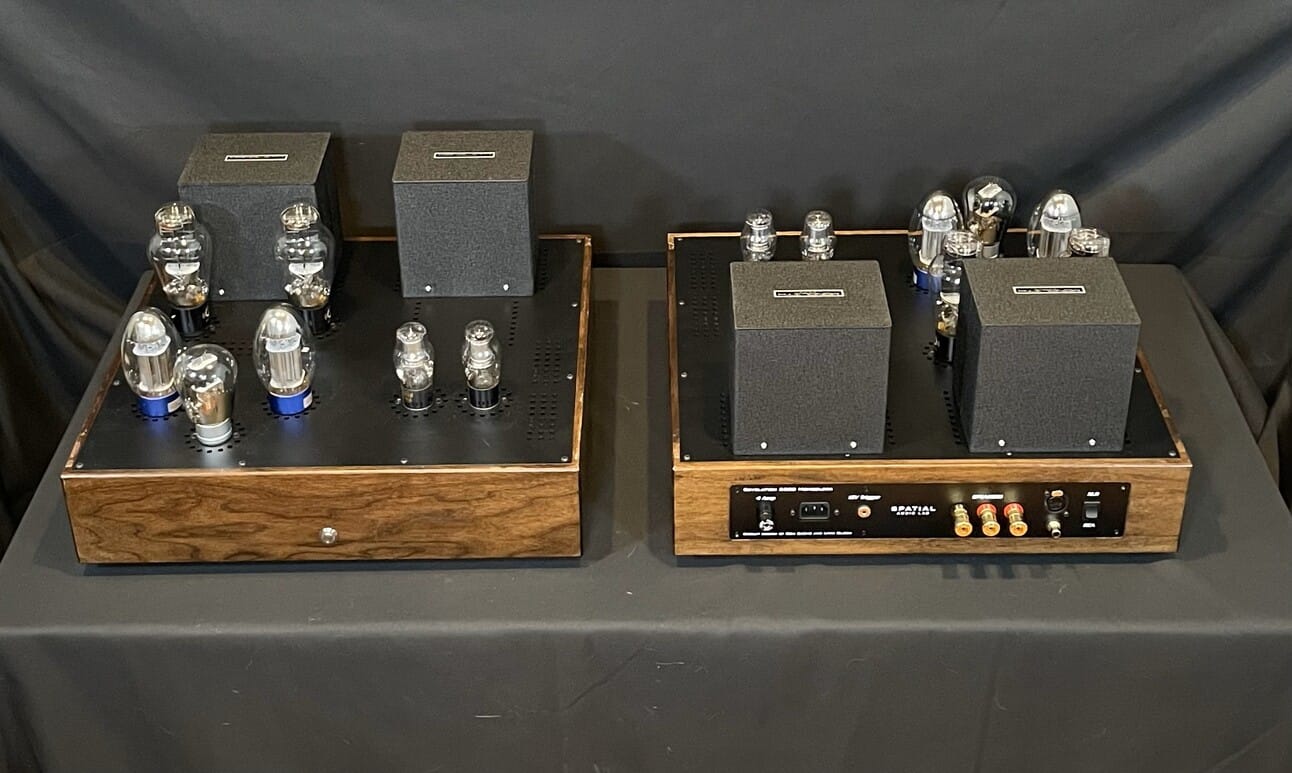
Spatial Audio now has the preamp and power amp in production (scroll down about halfway). The power amps are now 18" wide, the same as the matching preamp.
The tube lineup is 6SN7 input (balanced), triode-connected KT88 drivers, and 300B output in a fully balanced zero-feedback circuit. Monolith custom-design power and output transformers. The VR shunt regulators are on the right side of chassis, along with the power supply circuits. The audio circuits are on the left side, isolated from the power supply by an under-chassis shield running from front to back.
Revelation Series
|

Still making small production changes to the Revelation Series power amps and preamps. The main B+ power supply choke (filter) is now from Monolith Transformers and is on top of the chassis, along with the output transformer and the power transformer.
|
Spatial Audio at the Southwest Audio Festival, with the new Q3 dual 15" dipole speakers and the latest Revelation Series Raven preamp and Blackbird power amps. The pint-sized Mola Mola Tambaqui DAC is tucked behind the Raven preamp.

|
If Spatial is at the Seattle show this year, yes, I will be there. I had a lot of personal stuff that precluded my attendance at Dallas, but it sounds like the SWAF was great experience and a good time for all.
Don tells me there is a lot of serious tech in the new Q3 speaker, and of course Don and I have rolled in a lot of new tech into the preamp and power amp since the Seattle show.
I expect I’ll be working with Joseph Troy Crowe on completing the notorious "Beyond the Ariel" speaker project started many years ago on DIYaudio. This will be a non-Spatial project, just between me and Troy, but it will be open-source.
My work with Don and Spatial will continue ... in the short term, I need to write the product manuals. If there is demand for new electronic products, I will be part of that, but Spatial designs their speakers with their own design team in Salt Lake City.
|
Yes, I've come to the conclusion that speakers and power amps are about 50/50 responsible for overall sonics. Based on measurements, you'd think that speakers are responsible for 90% of system coloration, but in practice, no. The amps have a big role, too.
|
I got into the amp game after auditioning both the Audio Note Ongaku and the Reichert Silver 300B on speakers of my own design. I’ve been designing speakers since 1975, so I have a pretty good idea what goes in them and why they sound the way they do. Crossover design errors, diffraction artifacts, enclosure resonances, driver breakup, etc. are things I usually hear in a few seconds when I listen to commercial speakers. So I know speakers pretty well.
What surprised me was the Ongaku and Reichert revealed things about my speakers I did not know were there. And different things between the two: the Ongaku revealed "space between the notes" in a way I had never heard before, as well as extraordinary, almost uncanny spatial realism. The Reichert deepened the emotional response to the music in a way that was outside the audiophile experience and not anything to with coloration or tonal balance. It was just a feeling, even when I was listening objectively and trying to assess what I was hearing. It just snuck up on me with a powerful emotional response.
It’s one thing listening to a commercial speaker that’s off-the-shelf with unknown design goals, semi-custom drivers, and unknown crossover design, but quite another when the speaker is something you’ve taken from initial conception to successive versions to final prototype. You’ve pretty much heard everything it can do, and have already built 13 different crossover variations and auditioned it on eight different amplifiers. You know that speaker inside and out.
And yet my speakers had undiscovered sonic aspects that were NOT part of source impedance (damping factor) or audible amplifier coloration. Things I’d never heard before. What kind of "distortion" gives MORE resolution, or a deeper, more profound emotional response? That’s nuts. Nonlinearity is not our friend; it steals resolution and separates you from the music with a haze of coloration.
So what’s going on here? That’s when I started researching the history of vacuum tubes and started writing for different audio magazines. I don’t believe in copying or "cloning" the designs of others; not only is it dishonest, it reflects a lack of understanding on why a product sounds the way it does. You have to understand the "why" before you can go any further, and that took about five years before I came up with the Amity in 1997.
Amplifiers are not as neutral as we would like them to be, and an amplifier with measured distortion in the parts-per-million range is not necessarily neutral sounding. They all have a sound ... Class D, GanFET, bipolar transistor, pentode, triode, and direct-heated triode.
|
To the best of my knowledge, the price of the preamp is $5000. Possibly less when purchased as a bundle with the power amps. The XLR output should be AES compliant, driving both phase equally.
|
|
I fully defer to Don, who is part of the loop of the Spatial team, who manufacture the preamp and power amp. I’m more like the system architect, guiding the project in a certain direction, and I’m not as aware of the manufacturing and production side of things.
One benefit of the output transformer in the preamp is it does accurate phase spitting, even if there is a small gain mismatch in the 6SN7 tube. Other balanced designs tend to rely on feedback for output balancing ... the Raven is zero feedback, either global or local, so transformers do the balancing and unbalancing conversions.
The input transformers are bypassed for the special case of XLR (balanced) sources. For example, many DACs have XLR outputs, since many converters inside the DAC have balanced outputs. On the other hand, tube phono preamps are often single-ended, so have RCA outputs. The Raven caters to both, with a source selector on the remote control. The Khozmo volume control is fully balanced, and so is the 6SN7 that follows it.
|
The Raven is not very sensitive to loads. In practice, power amps range from 10K (typical solid-state) to as high as 470K for a handful of vintage tube amps. Most modern tube amps are 100K. Plus whatever cable capacitance is there, along with the Miller capacitance of the input section of the power amp. So 100 to 400 pF is typical. The range of loads is predictable and well known.
What dominates the transformer performance is the source impedance, not the load. The source impedance from the preamp tube is much lower than the load, so it heavily dominates the transformer performance. Transformers don’t much care where the low impedance is, primary or secondary, so long as it is there.
The hard transformers to design are the interstage transformers, since they are driving nothing more than a grid (without grid resistors). So the load is effectively nothing more than the Miller capacitance, which is fortunately a known quantity and can be designed around. Similarly, the source impedance is also known, since it is the plate impedance of the preceding tube. We use transformers that are purpose designed for the impedances and the power range they will be exposed to in-circuit. (Not off-the-shelf general-purpose transformers.) One nice thing is our transformer designer has access to modern magnetic simulation tools that were not available back in the Thirties and the Fifties.
|
Of course, it is tempting to design a special-purpose headphone amp. I own HifiMan HE1000 Stealth (V3) planar headphones myself, and I use a modest all-in-one DAC/headphone amp to power them.
But ... the headphone amp market is quite crowded, and is dominated by Chinese products selling from $200 to $1600. On the domestic front, Geshelli is cleaning up making AKM-based DACs and Sparkos discrete-opamp headphone amps at entry-level pricing. As far as I can tell, headphones, and headphone amps, is the most competitive sector of the audio market right now.
So even if we spent several months to a year on a special headphone amp, I’m not sure we’d sell many. Something to think about, though.
|
In terms of load abuse, plugging planar headphones (20 ohm to 32 ohms) into the Raven preamp will definitely load down the preamp and is not recommended. No harm will result, but the preamp will slide over into Class AB operation and distortion will rise to higher levels. Headphones with impedances of 300 ohms or higher (most dynamics) are fine.
We may design a future project that can accommodate planar headphones, but these require a genuine 1 to 2 watt Class A power amplifier, which is outside the scope of a preamplifier intended to drive power amplifiers. In other words, a tiny but very high quality power amp with extremely quiet power supplies. Designing (good) amplifiers for planar headphones is not as simple as it appears at first glance.
|
Ralph, I see you introduced a PP 300B amplifier at one of the recent hifi shows. How do you think it compares to your Class D amplifier, in subjective terms? Since you designed both, you're the best qualified to assess the differences.
|
One of the nice things about working with Cinemag is their custom design service. This gets us away from the many limitations of standard off-the-shelf transformers from other vendors. We specify source impedance, the range of loads (including capacitance), DC current flow, and expected DC imbalance. They show us what their computer model tells them, we test the physical prototype, see how it works on the bench and in-circuit, and go back and forth a few times until everyone is happy. Off the shelf, it's take it or leave it.
This is what made both the Raven and Blackbird possible. I didn't think a transformer using the 6SN7 in balanced mode could be realized because of the quite high impedances involved. To my surprise, Cinemag showed me otherwise ... very clean square waves at 10 kHz with minimal overshoot. This is not an off-the-shelf part ... it's been designed for us.
When we say the Raven and Blackbird use custom parts we aren't joking. Without them, they aren't practical. We use standard tube types because we want our customers to enjoy them for a long time, and we expect the 6SN7, KT88/6550, and 300B to be around a long time. Under the chassis, though, we use custom parts for critical functions.
|
Wow, is that the first Atma-Sphere with an output transformer?
Sounds like the 300B amp is well on track, and I imagine the next version will have current sources in the appropriate positions. I’m curious what your experience with a high-power current source in the output stage turns out to be. It didn’t work for us, but it did work for Allan Wright back when he visited me in the late Nineties.
|
Yes, it’s difficult to get people to understand that Class A push-pull is quite a different animal than the much more common Class AB push-pull. I understand the reasons for Class AB ... it’s much more efficient, but Class A working is not the same, since device switching and the saturation region are avoided.
It’s also kind of funny seeing the solid-state fraternity tap-dance around various sliding-bias schemes and the marketing attempts to call them "Class A". Well no, they’re not, since the clever sliding-bias system is always just a little behind the musical content. And genuine (thermal) Class A transistor amps require stupendously large heat-sinks or fan cooling.
I remember all the marketing about "cool-running" transistor amps in the late Sixties. Yes, they ran cool if the Class A region was 1 watt or less, and the rest of the operating envelope was Class B. The A/B switching region was especially offensive with the quasi-complementary amps of the first and second generation. The third generation, in the late Seventies, finally had access to decent quality complementary devices, although dog-slow by modern standards.
Class A working is actually easier with vacuum tubes, since you don’t need a monster heat sink. Solid-state reliability drops pretty fast above 80 deg C, so heat sinks and efficient thermal design are mandatory. By contrast, vacuum tubes operate quite happily at very high temperatures (short of red-plating). If you can accept lower power, it’s easily within reach by altering bias points and the primary impedance of the output transformer.
I agree with you about the merits of single-ended vs Class A push-pull (or balanced). The only indisputable advantage of SE operation is avoiding the zero-crossing region in the output transformer, but this comes at a massive cost in core size and the requirement for a large air gap, which in turn erodes bandwidth. Skillful output transformer design can work around the problems of the zero-crossing region ... this is largely a solved problem.
|
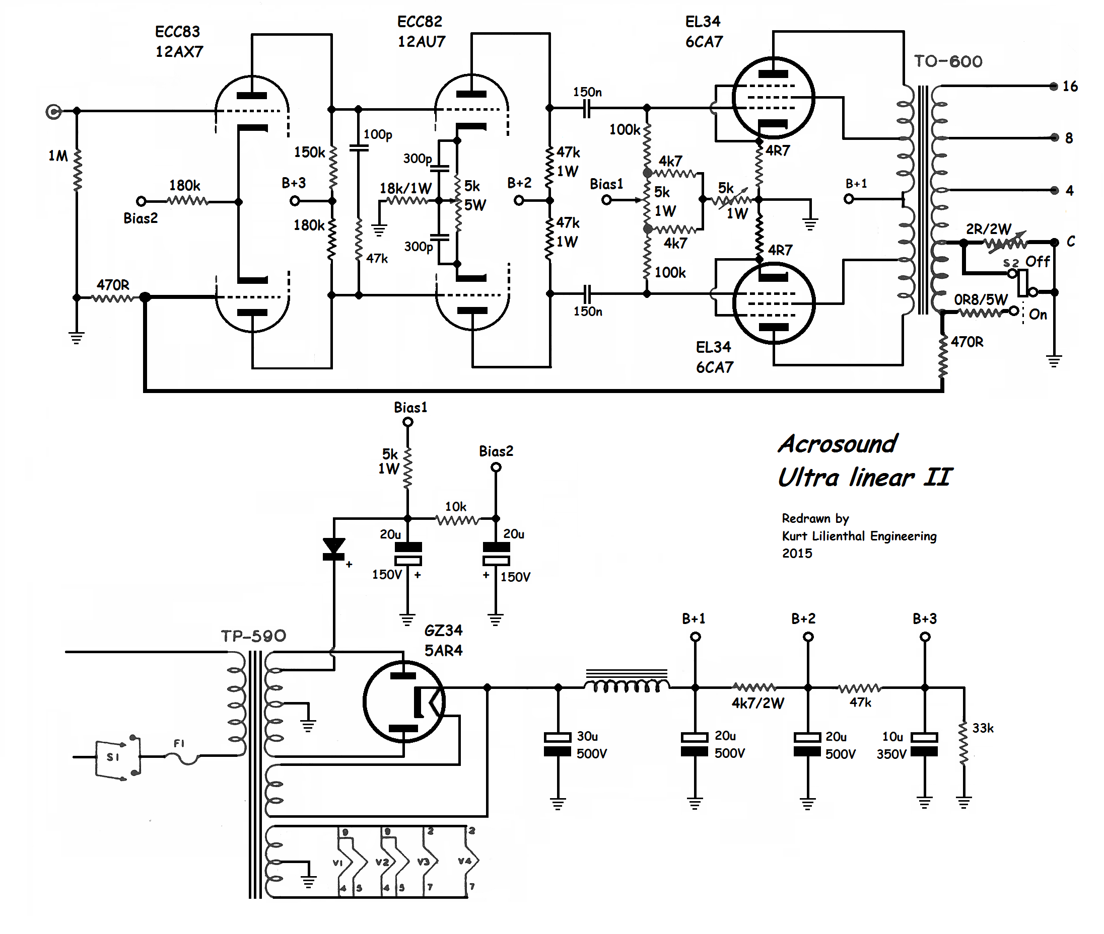
If all these transformers disgust you, or you want to use local or global feedback, you can re-visit the Acrosound schematic from the late Fifties. Three stages, all differential, each RC-coupled to the next. It can be easily updated with modern current sources on the cathodes, giving precise differential action and almost no even-order distortion. The Acrosound circuit also offers some interesting options with cross-feed feedback between sections.
If you are bold, you can DC-couple some of the stages, but you will need good servo circuits to maintain DC balance as the tubes warm up and then gradually age. The servo circuits also need to be failure-proof, since a runaway servo circuit can destroy the amplifier.
|
Ralph brings up a very good point about feedback: the underlying theory assumes a distortionless summing point. (The summing point is the comparator input between signal input and the sampled output.) Any distortion introduced at this point of the circuit will be amplified without correction, and there is a real possibility of introducing new, higher-order terms that are not present in the forward path of the physical amplifier. Norman Crowhurst mentions this in passing in his Audio magazine articles in the late Fifties.
Don and I go to some trouble to avoid even local feedback in the Raven and Blackbird ... all cathodes are bypassed in every stage, we do not use the Ultralinear connection in the triode-connected KT88, nor global feedback. Any distortion that is present is the result of first-order effects in the tubes themselves, not anything else. It also mandates selecting tubes that have a minimum of high-order distortion terms in the intended operating range.
This overlaps with the philosophy of some SET amplifier designers, but we prefer to use complementary pairs to cancel most of the distortion without recourse to feedback (local or global). The transformers, if correctly balanced, cancel out most of the distortion before passing the signal to the following stage, thus, each grid-pair is fed a cleaner signal.
This comes in particularly useful for the 300B grids, which can be a difficult nonlinear load for the preceding stage. Unlike RC coupling, when one grid demands current, both phases of the driver pair are available to deliver current to the 300B grid that needs it. This enables seamless and jump-free transition to A2 (positive grid drive) when the signal demands it.
|
|
In essence, the signal flow is: Complementary Pair of 6SN7 sections -> Signal is re-summed in the transformer -> Complementary Pair of triode-connected KT88 drivers -> Signal is re-summed in the transformer -> Complementary Pair of 300B outputs -> Signal is re-summed in the transformer -> Loudspeaker Output.
To minimize interactions between output section and the rest of the amplifier, there are separate and isolated high-voltage regulators for input + driver section and the output section. The only signal flow, either from the audio path or the power supplies, is from input to output. There are no secondary paths, at least to the 130 dB limit of filter isolation offered by the power supplies.
A few SET amplifiers have a roughly similar signal flow, but only offer a few dB of RC filter stage-to-stage isolation between sections, so there is a signal backflow pathway between sections. Isolated power supplies resolves that problem. In a SET amplifier, 2nd-harmonic distortion builds up from stage to stage, but there can also be unpredictable level-dependent cancellation effects since signal polarity is inverted with each stage.
|
Just to confirm, the Raven and Blackbird do NOT use the Acrosound circuit shown above. The signal path is considerably simpler.
|
Acrosound UL-II schematic. Note the input 12AX7 is direct-coupled to the 12AU7 driver stage, so DC drift from internal 12AX7 mismatch could be a problem.
Technical analysis: The input signal goes to the top half of the 12AX7. The bottom half is connected to the feedback signal, which comes from a dedicated winding on the output transformer. The feedback summation occurs across the paired cathodes of the 12AX7. The plates of the 12AX7 are direct-connected to the grids of the 12AU7 driver.
There is a HF phase-adjust circuit from the 100 pF cap in series with the 47K resistor. This improves the stability of the feedback system. The 12AU7 driver has a 5K 5W current-balancing pot in the cathode circuit, most likely to correct for any DC imbalance of the 12AX7. I suspect the 300p marking of the bypass caps on the 12AU7 is in error. This should be 2 to 10uF, whichever gives the best square-wave response.
Similarly, there is a DC balance pot in the Bias 1 grid circuit of the EL34 output tubes. The 4.7 ohm series resistor in the cathode of each EL34 is there to meter current, which is adjusted by the 5K pot. Although not drawn, there would be test points for each cathode to ensure the correct bias point.
Although not marked as such, this is a fixed-bias output section set up for Class AB (high power) operation. Correct bias setting for each EL34 is essential for long tube life.
|
Very pretty! Which driver tube?
|
Before getting lost in the weeds on balanced vs single-ended phono preamp design, it might be useful to review the general types and look at their advantages and disadvantages.
1) The most common is a high-gain stage with RIAA frequency-shaping feedback wrapped around it. This dates back to an early Fifties RCA application book. Today, it’s what you get when you buy a $200 solid-state preamp ... a modern high-gain opamp with a feedback loop wrapped around it. It has the merit of low cost and simplicity, and if done in the Fifties style seen in many preamps, a traditional sound many like.
The drawback is using a low-current device like a 12AX7, which typically runs at 0.5 mA current, which does not have enough current to drive a moderately long cable and the reactance of the feedback loop at the same time. This leads to the preamp creating slew distortion with record pops and mistracking, which exaggerates their audibility.
2) A new/old approach is splitting the RIAA equalization in two, using it as a passive filter between the first tube (for the first filter) and second tube, and a second passive filter between the second tube and the third tube. The RIAA filter is usually split in two to avoid overload and noise problems that build up with a single passive RIAAA filter with a 40 dB attenuation loss between tube sections.
This passive-filter approach requires a judicious balance between noise buildup (mostly a problem in the first section) and overload, which can easily happen if the stylus starts mistracking (which is much more common than you might expect).
3) One of the more offbeat new/old approaches is a passive LCR filter between sections, using well-shielded inductors as part of the RIAA network. This is usually a pretty exotic part, and the first stage needs enough linear current to drive the highly reactive LCR network. I have heard this type of preamp and was startled by its naturalism and lack of phono preamp coloration. But they are exotic and difficult to design.
I should add that phono cartridges are often blamed for phono preamp coloration, which mimics mistracking and common types of cartridge coloration. Most phono preamps, whether solid-state or vacuum-tube, are actually quite colored and prone to HF distortion, making many records sound shrill and distorted. The best ones reveal surprisingly quiet record surfaces as well as open and natural high frequencies.
Before doubling the complexity of the phono preamp by using a balanced circuit, it first has to have a noise floor lower than the tape hiss recorded on the LP record, and more seriously, be free of slewing distortion and overload. This is subjective, but I hear clear and obvious overload on most preamps I hear at hifi shows. The exhibitor may blame the phono cartridge or the record, but a preamp swap will reveal the distortion is actually in the preamp itself, not the cartridge. Although phono cartridges are often flawed, many phono preamps make them sound much worse than they really are.
It may be a crude standard, but above all else, components should never audibly overload on any record, no matter how badly it is mastered. It does no good to have an expensive hifi system that can only play a handful of audiophile-approved discs that have been very carefully mastered. It should be the other way around: the preamp should accept ANY disc without breaking up, distorting, or becoming shrill. That’s much more important than pushing the noise level 3 dB lower than any record ever made.
|
A quick note on the complex variable equalization seen on the Citation I: people who had extensive 78 and pre-1955 LP collections had records with wildly varying equalization curves. By the time of the stereo LP in 1958, the world had settled on the RIAA system, and all stereo LP’s use RIAA equalization (to the best of my knowledge).
Some early (mono) LP’s had the EQ marked on the label or the record jacket, or the record company was known for having a house curve, but 78’s were notorious for being all over the place, with no industry standard at all. Even the speeds vary, with 78 rpm merely being the industry average.
So the super complex switching on the Citation is mostly aimed at the record collector with a lot of mono records, both 78’s and LP’s. Some folks even kept their old mono preamp, just to play their old records with varying equalization. For that matter, tone controls were very important in the Fifties, and were still important in the Sixties.
Few speakers were flat, and record companies usually had a house sound, or actually several house sounds, depending on the musical genre. Elvis on a 45 single was not going to be treated like an RCA Red Seal classical record, and the early Beatles sound was very different on the US Capitol release than the Parlophone release in the UK. Tone controls were standard on all hifi equipment back then.
Just to boggle your mind a bit more, cutting a lacquer master from the two-track master tape meant the engineer "riding the controls" as the cutterhead neared the center of the record. Different engineers would have their own interpretation of what the master should sound like ... so yes, there can be many "master records", not just one.
P.S. If I'm reading that schematic right, the Center Channel output, although correctly summed from Left and Right, is actually out of phase with both of them. (The 12AT7 inverts phase.)
|
Well, keep in mind most LP’s were cut with spherical styli in mind ... specifically, the Stanton 681A with spherical styli. Over in Europe, it was the Ortofon SPU with a spherical stylus. Both were used to play the lacquer once for quality control, then off to the plating plant.
Ellipticals were fairly rare in the Sixties and often poorly cut, with obvious asymmetries. In college, I had an ADC elliptical cartridge that destroyed several of my records until I wised up and bought the Stanton (as recommended by the early Stereophile magazine).
We didn’t see Shibata or Fine-Line profiles until CD-4 quadraphonic records, with their 30 kHz FM carrier on each groove, required for adequate CD-4 playback. That was 1971 or so, if memory serves. The trick with Fine-Line profiles is azimuth needs to be *exactly* right, within one degree, or mistracking gets pretty bad. With sphericals, azimuth hardly matters, and even ellipticals are moderately tolerant of misalignment. But not Fine-Line profiles. They need to be exactly on the money.
One of my minor inventions with the Shadow Vector quadraphonic decoder (Patent #4,018,992) was an electronic crosstalk cancellation scheme, which electronically rotated the axis of the two generators so they were precisely at 45/45 degrees. That gave about 45 dB of measured separation, with an optional second-order corrector which operated above 10 kHz. That corrected for cantilever twisting at high frequencies, a problem I noticed happening with many cartridges.
Shadow Vector quadraphonic decoder
I was not thrilled to discover many $2000 to $15,000 cartridges had visibly rotated cantilevers ... not by much, but by about 2 or 3 degrees, which made azimuth adjustments extra tricky. With a Fine-Line stylus, nearly mandatory at that price point, you have to get the stylus exactly square in the groove, regardless of the generator axis. Which is where electronic compensation comes in ... if the generator is not at 45/45, you can rotate it electronically, and get the separation back with no penalty.
P.S. The crosstalk cancellation is very simple. Each channel has an adjustable amount of crosstalk from the other channel, with plus-phase crosstalk on one side of the pot, and minus-phase crosstalk on the other side. In the center of rotation, zero crosstalk. One pot for each channel, a test disc, two quick adjustments with a meter, and off you go. 45 dB or better separation from any record or cartridge.
P.P.S. That EAR schematic looks kinda sketchy to me. I would not use it. I suspect the errors and the wonky drawing style are intentional.
|
Some fixed-bias amps have a separate servo circuit that monitors the bias of each tube, so user does not need to adjust the amplifier. This servo circuit needs to be very reliable, though, since a failure would destroy the output tubes, and possibly damage the bias circuit, as well.
Cathode bias, which is nothing more than a power resistor bypassed by a (very) high quality capacitor, acts like local feedback at DC, and more like fixed bias at audio frequencies. It is not suitable for Class AB amplifiers, though, since the total current going through the pair (or more) of output tubes varies with the power delivery (the efficiency actually goes up as output power increases). By contrast, Class A operation has more or less constant current draw from the output pair, but it is significantly less efficient than Class AB.
|
By the way, the traditional definition of "efficiency" is: (Max RMS output power at stated distortion level) / (Total power going into the plate circuit). Power consumed by heaters, filaments, input and driver tubes, or regulators is not usually considered.
For a pair of output tubes ... 6V6, EL84, 6L6, EL34, KT88, 6550, 2A3, 300B, 845, or similar ... they can be set up to run in either Class AB, or Class A. Class AB operation typically has a higher B+ voltage and a lower quiescent (steady-state) current, while Class A operation has a lower B+ voltage and a higher quiescent current. For the same average power draw, Class A usually puts out half to one-third the output power of Class AB, which is why it is less common than Class AB.
Most customers want more power if they have a choice. That was true in the Fifties and it is still true today ... partly because most loudspeakers are very inefficient (less than 1%) and need all the power they can get.
|
I left the driver tuning up to Don Sachs, who’s been building PP pentode amps for decades ... and started out by restoring Citation I and II’s, which are notorious as the most complex amps and preamps of the Golden Age. By contrast, the Marantz amps and preamps were much simpler.
Don’s a big fan of the 6V6, 6L6, and KT88 (in triode mode). Kind of hard to argue with that ... some of the most famous amps ever made used those tubes. Anyway ... he tried about every well-known tube under the sun as drivers. I kind of thought something as petite as a 6V6 (which is equivalent to a 45 in ratings) would be optimal, but the KT88, running at fairly high bias, sounded best of all. Part of the reason this is relevant is the 300B is very, very sensitive to the driver tube, much more so than most tubes.
The 300B has a difficult combination of very low inherent distortion (bested only by a 45 triode), and a grid-drive requirement of 80 volts peak at very low distortion. In most commercial 300B amplifiers, all you hear is the distortion of the driver, especially if it is RC-connected. You never hear the 300B as it really is. All the usual complaints of dull, soggy sound are the result of a not-good-enough driver.
Get a powerful enough driver with enough current (30 mA or more) and transformer couple it to the 300B grid, and you hear a very different sound ... very fast thanks to the high slew rate, and very wide-open thanks to low inherent distortion. Yes, I know about the Sakuma-san 300B - 300B amplifier ... I met him and heard it at one the last VSAC shows in Silverdale.
The Sakuma sound is mostly about the Tamura interstage transformers he favors, along with unique tube combinations. Surprisingly, my own Amity and Karna amps sound nothing at all like Sakuma designs ... if anything, our designs kind of echo the Citation I and II ... a big, fast, American sound, like a track-ready V8 Corvette. Sakuma would be more like a Morgan, very vintage.
Sakuma is 100% right about interstage transformer coupling. All the flavor comes through ... this is the unique hallmark of any interstage coupled amplifier. You hear it instantly, as soon as you walk in the demo room. Other methods subtly degrade tone colors, and all capacitors have an annoying tone color that is always there. I wish I knew what causes it, but it is not there in the cap measurements, unfortunately. But is very obvious when it is gone, especially after you get the last cap out of the signal chain.
Don and I valiantly tried to use various types of RC coupling between the input section and driver, some better than others, but the cap coloration was always there, no matter how fancy the cap was. They were all colored sounding, in various degrees, and a little dynamically flattened. So we had our transformer designer come up with a one-of-a-kind interstage to couple the input to the driver tube, and boom, problem solved. Simpler circuit, too. No caps in the signal path any more, and all the tone colors coming through ... which is the whole point of any vacuum tube amplifier.
|
|
The takeaway is that is impossible to "overdrive" the 300B. By contrast, a charmer like an EL84 can be driven with a whisper ... even a 12AX7 biased at 1 mA will sound good as a driver (which doesn’t work with any other power tube). A classic Mullard circuit is ideal for a pair of EL84’s since they are so easy to drive. 6L6's take a bit more muscle, so 6SN7's are a better choice.
The 300B is the opposite. A high voltage, high current, and ultra low distortion driver is mandatory, otherwise you never hear the 300B. You just get murk. 45’s and 2A3’s are a bit less temperamental, thankfully, with the 45 shining through with extremely low distortion.
|
The cathode circuit is quite sensitive to (subjective) parts coloration ... not surprising, because both grid and cathode are the two input nodes for vacuum tubes. The difference is the grid circuit has very low current flow (but not zero) while the current flow through the cathode is nearly the same as plate current (the full audio signal). This means the full audio signal flows through the cathode resistor and the bypass capacitor, and the tube amplifies any errors in the cathode circuit the same way it amplifies any errors in the grid circuit.
Designers have been assuming for a long time that the grid current in normal Class A or AB operation is negligible, but I don’t think that is true for DHT triodes. They demand very high performance drivers with very low distortion into a complex load, which is where RC-coupling falls short.
The primary merit of transformer coupling is its efficiency, with 95% to 97% of the driver plate current available to the grid of the DHT triode. This is NOT true of RC coupling, where 30% to 50% of the driver plate current disappears into a plate-load resistor, where all it does is heat up the resistor. A dynamic load like a current source is more linear, but the transfer efficiency (between tubes) is no better than RC-coupling, so the unused current goes into a transistor heat sink instead of a resistor. Dynamic loads are also more complex if good performance is desired, with cascoded stacked MOSFETs, with secondary protection diodes, as the most reliable and best option.
Transformer coupling is absurdly simple, with no need for a grid-protection resistor, no coupling cap, no plate load resistor, and no circuit board for the cascoded MOSFETs of a current source. Just wires going to tube sockets.
I suspect the 95% to 97% transfer efficiency of transformers is the reason for the vivid tone colors that are the hallmarks of any IT-coupled amplifier. You hear it immediately, which why Don and I hope more people can hear the Raven preamp with the matching Blackbird amplifier.
|
Well, I know more people than Whitestix bought the Blackbirds. My guess they are not on this forum (yet).
|
Interesting SET that harks back to the original Western Electric 91A, which also used feedback to get the desired performance.
I have mixed feelings about cathode follower drive: the output impedance of the CF is low (probably 100 ohms or so), but the peak current available is no different than anode drive. Considering the load is dominated by the Miller capacitance of the 300B (about 80 pF), the CF will definitely extend the small-signal bandwidth, but will have no effect on the large-signal bandwidth (also known as slew rate) which is determined by the (linear) current available to charge a capacitive load.
The small-signal benefits would be useful in a high-gain feedback topology as shown above, since it would improve phase margin at high frequencies, which in turn improves distortion at high frequencies. And the circuit shown above is definitely high gain compared to typical zero-feedback SET amplifiers; performance would be dominated by the feedback loop, not the 300B.
(Note for those puzzled by the schematic: there are two ground lines, not one, with the upper ground line at the top of the schematic. It winds its way down to the lower ground line, which ultimately connects to chassis ground at the RCA input at the lower left side of the schematic.)
|
Something both transistor and tube amps share are performance limitations set by current available to drive a capacitance. In a transistor amp, that will be the dominant pole capacitor associated with the second voltage-gain stage. The current available to charge that capacitance sets the slew rate of the entire amplifier. It should be mentioned that slew rate is similar to hard clipping; in slewing, linear operation has ceased, and there is no relation between input and output. As in hard clipping, there is a large region that is pre-slewing, with increased distortion but still a relation between input and output. With sinewave stimulus, the region of maximum dV/dT (rate of change) is actually around the zero crossing, which of course generates lots of high-order distortion harmonics.
Hard clipping and slewing have quite different origins; hard clipping is the result of one or more stages getting too close to the power rail, abruptly shutting off the gain stage. This can be either hard or soft, depending on the amount of feedback as well as the shutoff characteristics of the active stage. Transistors typically have a quite narrow shutoff range, with 0.7V being typical. Tubes are usually considerably broader, around 10 to 30V, depending on the device. This is also why tube rectifiers have a softer switching characteristic than solid-state.
Slewing, by contrast, is part of the amplifier running out of current, not voltage. Specifically, current available to charge a capacitance. Now, 80 pF isn’t much capacitance, but tube circuits are inherently high impedance (compared to solid-state) and operate at fairly low currents (again, compared to solid-state). The appearance on a scope are triangle waves, instead of flat-topped sine waves.
The somewhat arcane descriptor often seen in op-amp specifications is "large-signal bandwidth". This is another way of seeing slew rate: you measure output just below clipping and increase the frequency until the output begins to decline (which is the result of massive slewing). This measurement is simple enough for an op-amp and done all the time, but it can destroy a solid-state amp, so it usually calculated from quick measurements of slew rate.
Small-signal bandwidth is quite different and is usually measured well below clipping ... 1 watt is a common reference point. This is the result of various lowpass functions in the amplifier ... in a transistor amp, there is often a simple RC filter at the input that scrapes off unwanted RFI, which causes distortion in the audio band in solid-state circuits. Tubes are less prone to this but it is still not desirable to amplify AM radio signals at 500 kHz. In the tube world, the dominant lowpass is often set by the output transformer, which behaves like a 2nd-order (or higher) lowpass filter around 50~100 kHz. If a feedback circuit is wrapped around an output transformer, there needs to be compensation in the feedback network that phase compensates for this ... that’s the shunt capacitor you see around the feedback resistor ... but it must be tuned for that specific transformer, not just anything.
The Raven and Blackbird are non-feedback amplifiers, with the cathodes bypassed so local feedback does not apply, either. So there are no stability criteria or load stability issues. The distortion is simply the distortion of the matched pairs used in the preamp or amplifier. It has similarities to a SET amplifier in terms of a simple harmonic structure, but the pair-matching and balanced operation reduce distortion by about 30~35 dB ... without feedback or any associated stability or settling-time issues.
The approach Don and I take are borrowing elements of a modern SET and classical Western Electric designs from the 1930’s, getting the distortion as low as possible at the device level. This is where balanced operation and transformer coupling come in. The transformers of the 1930’s didn’t have much bandwidth, but they didn’t need it, since signal sources usually topped out at 8 kHz. Nowadays, of course, we need at least 30 to 50 kHz, which is where custom-designed transformers come in, using design tools not available in previous decades.
|
To recap, there are different challenges associated with low and mid-frequency distortion vs high frequency distortion. HF distortion is very often caused by nonlinear current delivery into a capacitance, and stray capacitance is everywhere in audio design. Sometimes you can reduce the capacitance using various methods such as cascode circuits, or pentodes (which are electrically similar), or take the alternate approach of increasing the drive current severalfold.
The 300B is a bottleneck in many SET amplifiers. The 80 pF load isn’t so bad, but the 300B requires 70 to 80 volts to clip it, and if the driver circuit is A2 capable, 100 volts. And ... the 300B has lower distortion than many, if not most, driver circuits, which defeats the entire purpose of using an expensive DHT like the 300B.
What looked like a simple problem is not simple at all, if you want to hear what the 300B actually sounds like, instead of a distorting driver stage. You have to deliver extremely low distortion into a capacitive load, over a range of hundreds of volts (if using PP output devices). This is no longer trivial. The common RC coupling seen in many amplifiers may not be up to the task.
We found transformer coupling with dedicated power tubes, themselves operating balanced Class A mode, gave the lowest distortion. Transformer coupling also allows A2 drive, with the 300B smoothly transitioning into the positive-grid region with no glitching. Although the 300B is not rated for A2 operation, we’ve found no indications of harm, although steady-state operation into A2 might overheat the grid, so not suitable as a guitar amp.
Now if feedback enters the picture, the design criteria all change. Forward gain goes up by as much as 10~20 dB, different parts of the circuit get optimized, and stability at high frequencies, particularly transient overload, become important. Nested loop feedback (2nd-order or higher) gives even lower distortion, but long settling times (after transient overload) can be problematic (because the different loops have different recovery times). You can have even more fun with modern feedforward techniques, but now we need serious computer modeling to pull that off and still have a stable amplifier.
|
Ralph, you’re the acknowledged OTL expert. How does an OTL amp work without feedback? I’d like to know. The last I checked, tubes designed for series regulator use like the 6080, 6AS7, or the Russian 6C33C have a Zout on the cathode side somewhere around 100 ohms. I’m not an expert on this class of tubes, but I wouldn’t expect any tube to have a Zout in the 8 ohm or less range.
(For the reader following along: a Zout of 8 ohms gives a damping factor of 1, a Zout of 2 ohms a damping factor of 4, and so on. Zout in the 0.1 ohm range, typical of transistor amps, gives a damping factor of 80. It should be mentioned that damping factors much greater than this are kind of pointless, since the speaker cable, which is in series with the DCR of the lowpass inductor in the crossover, will typically have a DC resistance of 0.1 ohm or so. I don’t expect speaker cables to use superconductors any time soon, so we’re stuck with copper or silver at room temperatures.)
I’ll admit this is kind of an idle curiosity since I will never design an OTL amplifier. The amps I’m interested in use transformers to solve various circuit-design problems. But I’m always curious how things work, whether solid-state, vacuum tube, or Class D, or hybrids of all three (like ZOTL’s).
|
That’s a subtle aspect of feedback theory that is often overlooked. The summing node must be distortionless, and also free of overshoot or slewing artifacts. Applying input signal to a grid, and feedback to the cathode, impresses tube distortion (of the input tube) on the entire feedback loop.
Of course, we can get in trouble with a differential circuit as well, since the summing node is spread across two grid/cathode circuits, not one. Assuming perfect match, the nonlinearities of the pair should cancel. In practice, we should expect 2~3% gain mismatch in the differential pair, so there will be a residue of mismatch and associated nonlinearity, but not much.
If I understand your previous post correctly, the Zout of a Circlotron amplifier will be high, maybe in the 10 ohm or higher range. Or there is local feedback somewhere in there, reducing it to "normal" levels of an ohm or less.
As you can see, Don and I are taking a brute-force approach to distortion reduction. Drivers that run at 40 mA per tube, and balanced deep Class A operation. The even-order distortion of the driver section is cancelled in the primary of the interstage transformer, reducing driver distortion even further. This presents a highly symmetric drive to the paired 300B grids.
|
It may strike some readers as weird that Don and I are taking a minimalist approach to a PP amplifier, more like a SET than a typical PP. The signal path is simple:
Optional SE/Balanced input transformer -> Balanced 6SN7 -> Interstage #1 -> Balanced KT88’s in triode in Class A mode -> Interstage #2 -> Balanced 300B’s in Class A mode -> Monolith Output Transformer -> Loudspeaker.
Similar to a fancy Japanese-style SET done twice. The hard part are the interstage transformers, which are not easy to find off-the-shelf, and ideally should be designed for the specific tubes in the circuit.
Don and I tried many variants to get rid of Interstage #1, since that operates at the highest impedances (thanks to the 6SN7) and is hardest (almost impossible) to design. The first version was simple RC coupling to the driver stage, with 6V6’s as driver running at 24 mA each. It sounded pretty decent and measured quite well, as you would expect from RC coupling. But Don wanted more ... so we tried paired dynamic loads for the 6SN7, which reduced its distortion about three times and was noticeably clearer sounding. But ... and there’s always a but, isn’t there ... there was just a faint trace of solid-state coloration from the current sources. Not much, but there. This was a version the folks at Spatial really liked, and we built some of the early "shoebox" format amplifiers in this format.
My grumble was the insanely long "burn-in" time for the super-deluxe coupling caps between the input and driver tubes. 50~100 hours. I am wary of burn-in times this long, since I suspect the part might be chemically unstable and never actually settle down, always changing its sonic presentation over time.
We tried another version, replacing the current sources with 100 Hy custom inductors. Was it any better? I’d say different, with deeper tone colors, no solid-state coloration at all, but losing a bit of snap and attack compared to the current sources. All expected ... no transistor sound, but unwanted stray capacitance in the high-value inductors, and question marks about linearity in the bass region.
Our transformer designer saw the high plate impedance of a balanced 6SN7 as a personal challenge, and insisted he could design an interstage transformer just for us. I was skeptical it could be done ... I only knew of one other transformer that could do that, from Tribute in Europe, and that thing was quite large and a one-off project done for the Karna amplifier. It might still be available from Tribute, for all I know. Tribute transformers are pretty special and the equal of any Japanese confection.
But ... a couple months went by, and Don got a special care package from our transformer designer. It was a pair of special custom Interstage #1 transformers, made just for us. Very simple wiring, compared to all the other variants we had tried, just six wires from the primary and secondary, as simple as it gets. In it went.
And that was the winner. Burn-in time was much faster, an hour or two, no super-exotic caps with their temperamental burn-in times, the circuit was way simpler, and the depth of tone colors was much deeper than any of the other versions. Obviously better than the inductor or current-source loads for the 6SN7, and no stinking coupling cap.
In fact, the IT coupling revealed the pretty obvious "cap coloration" of all the many coupling caps we had tried. The brutal fact is all caps have a sound, even though they measure extremely well. Worse, there is zero subjective correlation between sonics and the standard Df and Da measurements, not to mention they really do change sonics quite a lot over the first hundred hours. And nothing about that shift over the first hundred hours is measurable ... at all!
You hear the cap coloration by its absence. Go to true direct coupling, or IT coupling, and it is gone. After you’ve evaluated the sonics of twenty or more different brands and types of caps, you realize they all share a common coloration, with some much worse than others, but they all have something going on that is veiling the sound. And whatever it is, it can’t be measured with the instruments we have now.
I have no idea what it is. And I am taking about a coloration much more obvious than a cable swap between components. I’ll go out on a limb and say caps are the dominant sound of most tube electronics, whether preamps or power amps. Swap the coupling caps, and you have a brand-new amplifier, with brand-new colorations of its own. It makes you realize why there is a whole industry of guitar-amp tuning ... the tone coloration combinations are limitless.
But ... get rid of the caps, all of them in the signal path, and you are in a different sonic world. Do transformers have a sound? Well, if they are cheap transformers, yes they do. Murky and dull. The best, though, are very clear and have no cap sound at all.
That snap and clarity is what solid-state enthusiasts crave. Hey, I get it! The best solid state is very good and is free of cap coloration, as it should be. But ... solid state has its own sound, too. Unfortunately. Traces of it intrude on tube circuits if they have dynamic loads, or regulators that are not well designed. Don and I have gone to some trouble to use B+ regulators that are well behaved and have very high noise rejection (130 dB) and very low stray capacitance (using cascoded MOSFETs).
So I’ll go out on a limb (again) and say most audiophiles have never heard tube electronics without coupling caps. Ever. They think tube electronics just "sound that way" and tolerate burn-in times of hundreds of hours, with the sound changing hour by hour, sometimes better, sometimes worse, and sometimes just weird.
This plagues exhibitors at hifi shows, too, because the transport process results in some of the caps needing a re-set at the show, so the sound on Friday and Saturday can be remarkably different. And the culprit? Not the cables. Not the speakers. The coupling caps buried deep in the circuit, temperature cycling up and down, and going through unknown electrochemical changes deep inside.
And guess what? Solid-state electronics have caps too, not in the direct signal path, but as filter caps, typically large-value electrolytics. And you can bet they have a sound, too.
|
If you’ve been curious the kind of things two designers discuss with other, the previous posts give a simplified example. Sonics, different circuits and what they sound like, and reliability. It's also an example why collaborations between designers can result in designs that are better than any one person can do.
|