They’re different.
* Full-wave uses two rectifiers and only one half of the secondary at a time. Each active half-secondary switches back and forth 120 or 100 times a second.
* A bridge uses four rectifiers and the entire secondary all the time. The current through the full secondary switches direction 120 or 100 times a second.
That’s the most basic level. To a first approximation, full-wave transformers need twice the voltage for the full secondary, since only half the winding is used at a time.
In more depth, if there is a first cap following the rectifier(s), the rectifiers only conduct for very brief intervals (a few milliseconds) when the cap recharges. These brief, high-current pulses can shock-excite the half-secondary, causing ringing from the abrupt cutoff of the unused half-secondary. The shape of that shock is controlled by the on-off ramp of the diode, and if there are charge-storage effects from a solid-state diode.
The rest of the time, after the first cap is recharged, the diodes are switched off, and the amplifier is powered from the charge in the first capacitor. This cap is steadily discharged until the next pulse comes along and recharges the cap all over again. This charge-discharge cycle happens 120 or 100 times a second.
There's a tradeoff in sizing that first capacitor. If you double the size, the voltage sags half as much ... but the inrush current is also doubled, too. If you really overdo it, the inrush current will be so large it pulls the circuit breaker.
A "choke-fed" supply has the diodes directly feed a special inductor rated for very high voltages. The diodes remain "on" for most of the AC waveform. But ... the special inductor has to tolerate a significant voltage kickback when the diodes do cut off ... this in turn can create ringing and possible voltage breakdown of the windings in the choke.
All of these supplies create very large current pulses that radiate into the air and are are transmitted back down the power cord of the amplifier, which turns the cord into an antenna radiating a 120 or 100 Hz pulse train, with harmonics extending throughout the audio band,
A general rule-of-thumb in power supply design is to minimize the "loop area" of the most powerful transmitters, which are the loop created by the transformer secondary, the diode array, and the first filter element. Minimizing the wire length, tightly twisting these wires, and keeping them as far away from the input circuit as possible is highly desirable. This is why running AC power to a front-panel switch is undesirable from a noise perspective.
There’s a simple emulator called PSUD that lets you play with different power supply topologies and circuit values, and lets you scale the load to a real amplifier.
|
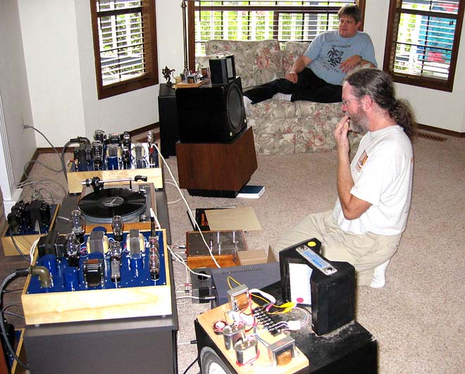
Yup. Wires, transformers, and 1930's vintage tubes. That's the entire signal path, from preamp input to speakers.
|
To complete the current loop around the 300B (or any other power tube), there has to be a low-impedance path from the cathode to the ground side of the filter cap of the B+ supply.
This can be (A) fixed-bias operation with the cathode at ground, or using something like a 10-ohm current-sense resistor. This requires an adjustable low-noise -80 volt supply, and a meter across the current-sense resistor. Adjust the minus supply until you have 70 to 80 mA flowing through the 300B. The plate voltage also has to be reduced by 80 volts or so, since you’re not dropping 80 volts across a cathode resistor.
A potential source of instability for the fixed-bias circuit is having a regulated minus supply while the main B+ supply is unregulated. Small variations in AC power voltage can result in large changes in bias point. The solution is either have a tracking feature for the minus supply, or regulate the main B+ supply, which is not cheap. In other words, when both ends of the tube are controlled by plus and minus supplies, they should track each other, or be fully regulated.
The (B), self-bias option is dropping 80 volts across a 20-watt cathode resistor, and bypassing it with 200 uF of film capacitor. B+ will be around 425 to 480 volts at the top of the output transformer primary. Sonics will be strongly affected by the quality of the film capacitor since it is in the main current loop of the 300B. Adjustment of current flow is not necessary since the cathode resistor provides a degree of negative feedback for the DC current flow through the tube.
|
The preamp, since it has balanced transformer-coupled inputs and outputs, breaks the ground connection between components, reducing hum, as well as RFI breakthrough and buzz. That’s why transformers are often used in noisy professional applications, and are used here.
This comes in handy for digital sources, since all ultrasonic noise (outside the 50 kHz bandwidth) is scraped off, as well as complete ground isolation. Rowland has been doing this for decades, and they're on the right track.
|
It turned out the ultrapath capacitor wasn’t sonically that different than a conventional cathode bypass cap. In the context of a regulated supply with an output impedance of 3 milliohms, and equivalent to a 2000uF passive supply, the Zout of the power supply is effectively zero compared to the cathode bypass or ultrapath capacitor.
By comparison, a passive CLC supply with a Zout similar to a 100uF capacitor, a ultrapath bypass might be more appropriate, but then the exact value has to trimmed against the noise introduced by the passive CLC supply. By contrast, the active regulator has 130 dB of noise isolation, so there are no issues of noise introduced by the supply and getting into the cathode circuit.
So it all comes down to the power supply. The optimal solution for a passive CLC supply, with its distinctive noise profile, might not be optimal for an ultra quiet supply with a very low output impedance.
And then we get into the deeper waters of the sonics of the regulators themselves. Some are slow and noisy, and intermodulate with the music. Others are fast and silent. Regulators do not all sound the same, and passive CLC supplies can have a signature too, depending on the capacitors chosen. There is no one-size-fits-all solution.
I should mention the battle of active vs passive supplies has been going on for at least three decades, and is somewhat biased by prejudice against the low-quality active regulators available 30 years ago. High-voltage regulators now are far better, and far more reliable, than what we had then.
|
The sonics of power supplies are different for SE and PP amplifiers, so it is impossible to generalize without specifying the amplifier topology.
The modulations of supply current on the main B+ supply in a single-ended amplifier are simply the music itself, with an addition of noise from the rectifier stack. Single-ended amplifiers are entirely Class A in operation, by the way.
This is not true for a balanced or push-pull Class A amplifier. The modulation of music on the supply is reduced by 30 to 35 dB (depending on balance), and what’s there is doubled in frequency, similar to a balanced-detector in a radio. The balanced-detector artifacts are the result of symmetric nonlinearities in the balanced pair ... if they have 100% distortion, you get a balanced detector.
If the balanced-pair distortion is a small fraction of that, say, 1% or less, then you still get balanced-detector distortion but much reduced in level. If the balanced-pair are 100% distortionless, then current draw is constant, with no variation. But distortionless balanced pairs exist only in fantasy, so there is always some variation in current draw with real circuits.
In a Class AB amplifier, it is worse, with three regimes ... Class A at low levels, and clipped-off Class B at higher levels.
This has an impact on the sonics of the supply. A single-ended amp is simple ... improve the musicality of the supply, since music is directly impressed on it. Push-pull is more difficult ... the modulations on the supply are a mix of residual imbalance and balanced-detector artifacts, and significantly worse if Class AB artifacts appear in the output stage.
This is the strongest argument for stage-to-stage isolation, so distortion artifacts from a high-level stage do not modulate a lower level stage, In the Raven and Blackbird, we go the additional mile by having a shunt regulator for the input section. The shunt regulator operates by having a current draw that is the precise inverse of the audio-circuit fluctuations, so the net current draw is constant.
By contrast, in a generic Dynaco or Mullard circuit, we have several topologies, with only simple RC power-supply filtering between stages. The output stage is typically Class AB semi-pentode, the driver is Class A triode, and the input is single-ended triode. All three have different distortion signatures.
|
|
|
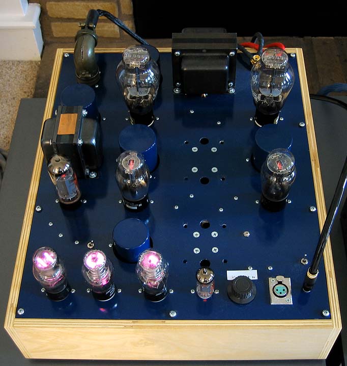
The Statements are the previous versions. I strongly urged Don to use a spacious layout, with all components on a single layer. Easier to build and signal-trace. Don ran with the suggestion and improved it by putting all the power supply components on the right side of the chassis, all the audio circuits on the left, with a shield between the two sections.
The wiring for the audio section, in particular, is really simple ... transformers, tube sockets, cathode resistors, and bypass caps. The wire lengths for each half of the circuit are symmetric, while cathode resistors, bypass caps and local grounds go to turret boards next to the tube sockets.
The bigger chassis also run cooler, as you might expect, since heat-emitting components are further apart, and the top plate is now 18" wide. The Blackbirds might look big, but they fit just fine on standard racks.
Sonically, the Statements and the Blackbirds are pretty close. They are all descendants of the original Karna amps, which date back to 2003. Unlike the Karna amps, the Statements and Blackbirds are on two chassis instead of four, which vastly simplifies grounding.
Here’s a picture of Gary Pimm (foreground) and Gary Dahl (background), taken in 2003. The Karna’s have the distinctive blue chassis, and the separate power supply chassis are behind the amplifiers. The AMT-1's are Gary Pimm's speakers.
|
Here’s a close-up of the 2003 Karna amplifier, showing one channel of the audio chassis, with the power supply chassis out of sight. These have been my personal amplifiers until I received a pair of Statements about eight months ago.
Note the aviation-grade Amphenol connector on the rear of the chassis. All connectors and cables are rated for 1.5 kilovolts, using transmitter-grade coax cables to carry the two separate B+ voltages to the audio chassis.
In case you are wondering what all these tubes are doing, the input tube is a 5687 (or 7119), the drivers are old-stock 45’s, the outputs are 300B’s, one pair of VR150’s are for the drivers, and a single VR150 is for the input tube. The single EL34 is a current source that feeds the VR tubes. The four blue-painted cylinders emerging from the chassis are General Electric industrial motor-run capacitors.
The Statements and Blackbirds are an update of this over-the-top project. I was doubtful the Karna could ever be manufactured until Don came along, with his lengthy experience making the Valhalla (KT66) and Kootenai (KT88) amplifiers. Not only is it more compact, the new Don Sachs power supplies are an order of magnitude better ... and they didn’t exist in 2003.
|
|
Here’s the latest: Don is training the folks in Salt Lake City as we near production.
The Raven preamp is the same preamp you heard at the show, while the Blackbird now has KT88 drivers, at twice the power of the 6V6 drivers, with third-generation Cinemag interstage transformers and Monolith output transformers, If you’re wondering who Monolith is, you heard them in the Songer room on the Whammerdyne amplifier.
Merry Christmas, Happy Hannukah, and a Happy New Year, to all!
|
1. If the heater windings are not shielded from the high-voltage B+ windings, switch noise from the B+ section can be capacitively coupled to the low-voltage heater windings. Although indirectly heated tubes have significant isolation from line noise, it is not 100%, so some of that switch-buzz gets through. If you listen closely, you will probably hear it.
There are several solutions: A) get a power transformer with electrostatic shielding (copper foil) between HV and LV sections B) go to DC heating with a regulator C) use a separate heater transformer.
When none of these are done, yeah, that’s cost-cutting, no matter how fancy the name brand. If swapping the rectifier tubes makes a notable difference in the sound of the amp, there’s something wrong, or not optimal, with the power supply design.
2. Yes, the two grounds must connect together at one point, and only one point, preferably the chassis. There’s an old joke: when two engineers get together, they will come up with three grounding solutions, and all of them will be right.
Grounds (and shields) should never float, ever. That’s bad practice and a possible safety hazard. Determining the best connection for the ground or shield usually takes a bit of thought (which is why it’s called engineering).
There are whole books on grounding. It is not a trivial subject. Part of the problem is language, because one word covers several things:
A) Safety ground
B) Current return path for the DC currents that power the tubes or transistors
C) Current return path for the AC audio signals going through the circuit
D) RF and noise shielding
|
From Don Sachs:
"First pair of production Blackbirds in walnut... running and sounding really good for only 10 minutes on them :)
Tomorrow we start the first pair of production Ravens...."

|
Alexberger, the Cinemag input and interstage transformers are under the top plate. These are the third generation of the custom Cinemag transformers we started with. The two Monolith transformers are visible on the rear of the top plate.
The other things under the top plate (right side) are the B+ and filament regulators, and the master soft-start circuit, with an external 12V trigger. The point-to-point and turret-board wiring under the audio side (left) is very simple, with only transformers, tube sockets, cathode resistors and bypass caps. No current sources or other gizmos.
|
And here’s the very first version, the 2-stage Amity amplifier, built on old Tektronix chassis by Matt Kamna in 1997:
|
If it doesn’t say "electrostatic shield" there’s no copper foil between windings. Medical-grade is even better, with primary and secondary on opposite sides of the core.
If you want full isolation, in the absence of these features, you need two transformers, one for HV, and another for LV. The name brand doesn’t change the shielding, or lack of it ... that requires copper foil isolation, which is a definite hassle for the transformer builder.
I should mention the heaters for the rectifiers do not need isolation. Only the heaters and filaments for audio tubes need isolation. If DC regulation is chosen, a higher secondary voltage than 6.3 volts is needed, since regulators need to throw away a few volts to operate. I should mention not all regulators are the same; you can do a lot better than generic 3-pin regulators.
|
I showed the pix of the Amity (1997) and Karna (2003) amplifiers to emphasize they were developed largely in isolation from the SET community. I found out the hard way that SET practice wasn’t always useful with this approach. Similarly, practice in the traditional push-pull pentode world isn’t always helpful.
Don’s build and design experience with the Valhalla and Kootenai has been very useful, showing me what worked, and what didn’t. So there are elements of the Amity, Karna, Valhalla, and Kootenai in the Blackbird.
Do they sound like SETs? No, they do not. Do they sound like traditional push-pull pentode amps with feedback? No, they do not. The signal flow and functionality is different. The closest similarity are to some unusual designs of the 1930’s, with the very latest 21st-Century transformers and power supplies.
The Blackbird is actually the result of a four-way collaboration ... between Don, myself, the transformer designer, and the power supply designer.
|
Just heard the first production Raven was completed, and the folks at Spatial Audio in Salt Lake City thought it was a big step up from the Raven preamp at the show. It uses a new Monolith power transformer, a newly designed input transformer, and VR-tube shunt regulators, in addition to the regulator used in the show preamp.
Like the show preamp and Don’s previous preamp, it uses a Khozmo volume control with a remote control that adjusts volume and balance, and selects inputs. Tube lineup is a pair of 6SN7’s (one for each channel in balanced mode), a pair of VR150 shunt regulators (one for each channel), and a pair of damper-diode rectifiers.
The Raven and Blackbird use standard RCA and XLR interfaces, so they can be used with other components, but they sound their best when used with each other.
|
Most likely not. It can drive 600 ohm phones no problem, but definitely not 16 to 32 planar phones, which are pretty popular these days. They require small power amplifiers in the 2-watt range.
|
As an overview, the Raven is a 1-stage amplifier with a 4.5:1 step-down transformer, and is output-limited by what both sections of a 6SN7 can crank out. The Blackbird is a 3-stage amplifier with a 28.7:1 step-down transformer, and is output-limited by what a pair of 300B’s can crank out.
The ideal solution for planar headphones is a 2-stage amplifier. For example, in the xDuoo TA-10R headphone amp sitting right next to me, a 12AU7 followed by a pair of Class A emitter-followers for each channel. Simple and inexpensive. Or, small power amplifiers in the 2 to 5 watt range ... all transistor, hybrid, or all-tube. The all-tube solutions ideally use step-down (output) transformers to match the load to the capabilities of the output tube.
Vacuum tubes can swing lots (hundreds) of volts, but are current-limited by peak cathode emission, typically measured in tens of milliamps, not amps. Bipolar and MOSFET transistors, in contrast, can pass not just milliamperes, but several amps, which is why they can be direct-connected to low-impedance devices like 8-ohm speakers and 20-ohm headphones.
A quick note on transformers: the voltage/current transformation ratio is the same as the turns ratio, but the impedance ratio is the square of the turns ratio. For example, the output transformer of the Blackbird, and many other other push-pull amplifiers, has a primary impedance of 6600 ohms, and a secondary impedance of 8 ohms. 6600/8 = 825, and the square root of 825 is 28.7228, which is close to the physical turns ratio. In a well-designed transformer, total losses are less than 5%, so can be neglected for this calculation.
So the output transformer of the Blackbird multiplies the peak current of the 300B pair by 28.7 times, offering peak currents of several amps to the loudspeaker. Similarly, the output transformer of the Raven multiplies the peak current of the 6SN7 by 4.5 times, which is plenty for driving a cable, but not really enough for planar headphones which mimic loudspeakers in terms of current draw.
|
|
|
Maybe Peregrine. Something fast and powerful, which are the hallmarks of these designs.
|
Don and the Spatial team will be in Dallas, but I will be home here in Colorado. If Spatial goes to the Seattle show this year, I will be there along with Don.
I learned my lesson about flying last year. This time, I’ll fly First or Business Class, and will wear an N95 mask while I’m at the airport. The show, though, was a lot of fun, and it was really nice staying at the show hotel and taking a nap in my room when I needed a brief rest. Also great meeting you folks in person, and seeing (and hearing) what’s going on in the industry.
|
For now, Don tells me he is focusing on the Raven preamp and Statement power amp. We expect to transfer production to Spatial Audio, with product names and prices to be determined. The circuits, parts selection, and overall construction technique are pretty much done, so what you hear in your home (the first pre-production run) and at the Seattle show, will represent what's coming.
Will Don continue to make his current preamp and KT88 power amp? That's his decision, not mine. My focus right now is the Seattle show and completing the large-format high-efficiency 2-way speaker Thom Mackris (Galibier Designs) and I have been working on for the last couple of years. (This design is completely independent of Spatial Audio, and an outgrowth of the "Beyond the Ariel" thread elsewhere.)
|
Thanks for the kind thoughts, whitestix. For those who are curious, this amplifier is a more advanced, second-generation Karna amplifier, first designed around 2005, and the result of a years-long collaboration with Don Sachs. More practical, two chassis instead of four, and benefitting from Don’s decades of experience in what works and what doesn’t, especially in a production environment.
My projects are usually proof-of-concept and kind of out there. Don’s experience makes all the difference for this collaboration, getting it off the ground and into the real world. He has a lot of great ideas, taking it even further, and these will be in the pre-production amplifiers at the Seattle show.
Whitestix, don’t feel left out. The amps you are listening to now are essentially identical to the show amps, just a little earlier in the production cycle.
It’s a fully balanced circuit, with 6SN7 input, 6V6 driver, and 300B output. It’s a high current, high speed design. I tested an early 2003 prototype at 500 kHz at full power, with clean-looking sine waves on the scope, with no visible flat-topping or triangle shapes. No, I won’t repeat that test again, and I don't encourage anyone else to do it, either.
|
Let’s discuss driver tubes. Back in the Nineties, my Tektronix friend Gary Pimm built a distortion analyzer that could measure each distortion harmonic, out to the 10th harmonic, down to an astounding -120 dB. Maybe even -140 dB. It was way, way down there.
So naturally Gary and I went and measured a bunch of tubes, and ran them at realistic drive levels (50 volts RMS or so). I knew from previous experience that audibility of 2nd harmonic is quite low ... I can barely hear 1% second harmonic, and audibility of 3rd harmonic is around 0.25%, if it’s mixed with somewhat more 2nd harmonic. (3rd by itself is harsh, but sounds pretty nice mixed 1:4 with 2nd harmonic, giving a richer, more fun sound.)
But the high-order harmonics are not nice sounding. Crowhurst suggested back in the Fifties weighting audibility of the order by the square of the order, or even by the cube of the order. High-order harmonics are what give electronics their nasty "electronic" coloration, and contribute very strongly with a forest of IM distortion clutter on the noise floor.
Unfortunately, unless the design is very poor, the relatively innocuous 2nd and 3rd order harmonics will dominate the THD measurements, to the point where THD is nearly useless for assessing sonics. When 2% THD is just barely audible, no, that is not a useful measurement. By that standard, all amplifiers are perfect.
But a spectral analysis is a lot more interesting, providing you pretty much discard the 2nd harmonic, and take a good, hard look at the rest, particularly the 4th on up. In a good amplifying device, you want 4th through 10th as low as possible.
We measured 300B’s from several vendors and vintage 45’s. Of all the tubes, these were closest to perfect. High-order harmonics were nearly absent, and of all the 45’s, none were visible at all. For 300B’s, they were way down, -60 dB or less, depending on the vendor.
That was one surprise. Most tubes, with a few exceptions, had comparable THD and 2nd harmonic, but the high-order spectra would vary within a given tube type by 20 dB, a huge difference. Twiddling the operating current made about 2-3 dB change ... not much ... but changing the brand would show much larger changes, 10 to 15 dB. We were plainly seeing differences in manufacturing technique ... uneven grid structure, tilted grids, etc.
The DHT’s were the clear winners in all categories, but the vintage 2A3’s were 10 to 20 dB worse than the 300B’s and 45’s. And the indirect-heated tubes were another 10 dB worse, or comparable to the 2A3’s. The worst tubes of all were the 9-pin miniatures, with the 12AU7 and 6DJ8 at the bottom of the heap. The 12AU7 had the decency to have lots of 2nd harmonic, which masked the clutter higher up, but the 6DJ8 had less 2nd harmonic and a harmonic spectra more like a transistor, with abundant high-order terms.
The 6DJ8 was a frame-grid tube designed for RF front ends in TVs and FM tuners, where linearity is of no concern at all, so you can’t really hold that against it. And the 12AU7 was designed as a compact replacement for the older 6SN7, operating at the same bias point and voltage. But ... high-order distortion is 10 to 20 dB worse than any 6SN7, even the worst. But you can’t hold that against it; 20 dB of feedback was universal when the 12AU7 was introduced. Loop feedback will reduce distortion in all tubes in the circuit, so it hardly matters.
The 6SN7 family is the tube of choice if you care about high-order distortion, and a DHT alternative is out of the question due to cost, size, practicality, microphonics, and severe filtering requirements for the filament supply. Of the 6SN7 family, the antique single triodes were the best ... 6J5, 6C5, etc. but there certainly were good 6SN7’s, both new and vintage. And differences were consistent within brands, reflecting manufacturing technique, and not always visible from the outside. Were the fancy MILSPEC ones better? Not really. More consistent, which is what MILSPEC is really about.
Don is correct that octals are (nearly always) better, unless you need a mike or phono preamp tube. That’s the 6DJ8 (or WE 417A) niche, where signal levels are very low, and noise and low microphonics are the primary concern.
|
RC coupling, although fast and compatible with overall loop feedback (highly desirable in pentode amplifiers), throws away about 1/3 of the potential swing (through voltage divider action) and also creates a steeper load-line, which increases distortion by 2 to 3 times (the load-line swings down into the low-current region).
But Job One in any feedback amplifier is bandwidth, otherwise the thing goes unstable. Can’t have that. So the rule of thumb is no more than one coupling cap in the entire forward path, plus the output transformer needs at least 60~80 kHz of bandwidth. The Williamson, which dominated from 1948 to 1956 in this country, was marginally stable unless you used the specified Partridge transformer, which had an astounding bandwidth extending to 120 kHz, and down to 4 Hz. So your options are limited if you want to wrap feedback around the amp ... only RC coupling, and only once per side, not twice, like the Williamson.
If there is no overall loop feedback, you can have any kooky topology you like, since phase margin no longer matters. But ... triode-connected pentodes have somewhat higher output impedances than DHTs (2 k instead of 800 ohms), and aren’t as linear. But this depends on the pentode. Don and I selected the triode-connected 6V6 because 1) 45 tubes are near-unobtainium these days 2) 6V6’s are reliable, been around forever, much loved by guitarists for their famous tone, and oh yes, sound good too. Last but not least, the 6V6 was purposely designed as the replacement for the 45 in radio use, so operating points are very similar.
Part of amp design is deciding what "tone" you want. Because it’s going to have a sound, no matter what technology is there ... Class D, MOSFETs, bipolar transistors, pentode, triode, or DHT. No matter what you design, it will have a sound, no matter what you do, or how clever you are. The perfect component does not exist. The designer needs to steer that little touch of coloration in a good direction. Fortunately, Don and I are on the same wavelength ... I’m looking forward to meeting him at the Seattle show, in person. Should be a lot of fun.
|
Pindac brings up a good point. Designing a good amplifier is a lot of work, and there’s just as much work getting a product market-ready. The input and output tubes were obvious choices, based on subjective sonics, low distortion, and continuing availability. The challenge was the driver.
Low-powered DHTs have a very small niche market, so have extremely high prices, and it is an open question if they will still be available five or ten years from now. That was a question about the 300B back in the Nineties when the Triode Revival began, but it has been answered ... the 300B has created its own market, and is manufactured in several countries. It has joined the 6V6, 6L6, EL34, EL84, KT66, KT88, and 6550.
The requirement for this amplifier was a wideband driver producing about 2 (or more) watts of very linear Class A power. The first Karna amps used a quartet of hand-matched vintage 45’s. If they were scarce in 2005 when Gary Pimm built the original Mark I Karna’s, hoo boy, they are insanely rare now. Or built only in Germany at frightening prices. Yes, there several Euro-made low-powered DHT’s. All different from each other, with different bias requirements, and some with different pinouts. All very niche products.
The Chinese 2A3’s are interesting. They have single plates, unlike the twin plates of the RCA original, and look a lot like 300B’s with 2.5 volt filaments and somewhat de-rated emission. I’m not quite sure where they fit in the DHT world, but people seem to like them, and demand appears steady.
And then there are the real odd ducks, the Chinese 101D’s. Wow. These are really out there, a tube that hasn’t been in production for ninety years, and extremely scarce in the collectors market, far more so than 45’s. Will they still be produced five or ten years from now? Who knows?
Don and I played it safe. There are zillions of old-stock 6V6’s out there, and a large continuing market for them in guitar amps, much larger than the hifi market. Whichever tubes we selected for this amplifier, and the new preamp, we wanted replacements to be available well into the future, and entertainment value in pawing through old stocks, if the owner wants to do that. All we ask is the pairs be well-matched, both for sonics and optimal performance.
|
As mentioned above, the Mark I Karna used a quartet of 45 tubes, but new production is limited at this time, with future availability an open question. Five years from now? Maybe, maybe not. Ten years? Maybe, maybe not. I can only go by popularity in the market and how many different vendors, in different parts of the world, are currently making them. Not just one factory in one country.
For a DIY hobby amp, availability of tubes not a real concern. But if people are buying a commercial product and expect service (warrantees are a legal requirement in the USA and Canada), availability of new-production matched pairs is a major concern. Don and I looked at the market and we both decided, nope, not yet, still a pretty specialized niche product, and NOS and old-stock supplies have all disappeared into the collector market. When the Mark I Karna was built, they were scarce, but could still be found. Now they are very scarce indeed.
As for sonics, for anyone that’s designed an amplifier from scratch, as I have, the sonics of the 300B are largely determined by the linearity and current delivery of the driver stage. Most of the commercial 300B amps I see at hifi shows have driver stages that are under-designed by a factor of 2 or 3, which results in not enough current to drive the Miller capacitance of the 300B grid. They aren’t as hard to drive as an 845, which is nearly impossible, but they are only second to an 845. A good driver needs high current, high linearity, high speed, and enough headroom to drive the grid 20 volts positive and then recover in microseconds.
Most drivers can’t do that, so the driver and output both clip at the same time, and then both have different recovery times, which can last an appreciable fraction of a second for RC-coupled amps. A typical SET will have RC isolation for the B+ supply between stages, and that RC filter has a characteristic recovery time once a stage saturates. So four things have to recover after saturation: the RC coupling between stages, the RC isolation B+ filter between stages, and cathode bypass caps for each of the cathodes. Typically, they all have different recovery times. Then we get into the subtler issues of capacitor coloration, which can overshadow tube coloration if the caps are not well-chosen.
Most of the "sound" of a conventional SET amp is simply a driver that has run out of linearity. The same is true of preamps, by the way. They run out of linear current to drive the interconnect cable capacitance and then the power supply folds down as it is saturated.
|
One of the really fun things about designing an amplifier from scratch (not from 1950’s schematics) is you can hear for yourself when you make a change. Reviewers can only treat these things as "black boxes", and customers can only work at the margins with cable swaps. Don and I can change topologies, power supplies, tubes, basically everything.
Every change is audible, but some are far more important than others. Driver design is right at the top of the list. That’s what makes or breaks an amplifier. I wish more designers understood this.
I shouid add there is no 1950’s or 1960’s tech in the power amp or preamp. All of the tubes were designed in the 1930’s, and the circuit is a combination of 1930’s and 21st-century tech. No relation to Golden Age tech, in other words.
|
|
Fortunately, Don and I know where the "bad actors" are, and it’s no secret. Caps. Specifically, film caps. They’re the parts that need the 10 to 50 hour run-in. I do not like this ... it suggests the plastic film is undergoing a very slow chemical change while it is being charged, and a further change when the charge is modulated by an audio signal.
But direct-coupling is a whole another can of worms. The worst is that failures in one part of the amplifier cascade through the amplifier, and can even destroy loudspeakers. This is the typical failure mode of solid-state amplifiers ... a DC servo circuit, or voltage regulator, fails, and then destroys everything that is DC-connected to it. Cap-coupling or transformer coupling limits the failure to one part of the amplifier, and limits the scope of the failure to no more than a few parts.
Also, Don and I have prior experience and expectation to guide us when we try XYZ change. Is it audible at all? Is it better or worse, or just different? I don’t know about Don, but I can hear changes in ten seconds or less, and have a better, same, or worse reaction, or sort of a mixed feeling.
The mixed feeling is a danger sign and indicates that there’s something I don’t like but can’t describe or pin down. That’s pretty common at the serious design level, by the way. You often hear or feel things that just make you uneasy, which is a sign to turn it off immediately and take a good, hard look at the circuit and see what you missed. Maybe a wiring error. Look again. Stop, think, reflect, do something else. It happens to us all.
Yes, fresh film caps often sound dull, flat, and dynamically compressed. There are often subtler colorations I describe as "glossy" or softened, a kind of over-processed Photoshop impression. You hear it a few times, and you know it immediately.
But compared to an outright circuit error, that’s nothing. Those sound much worse, grainy, shrill, shouty, almost always something very very wrong, and almost always in the high frequencies. Does it sound "electronic"? Yeah, that’s bad. Find out what’s wrong. Look hard enough and you’ll find it.
|
Last but not certainly not least, my collaboration Don Sachs, which began with phone conversations and many, many emails after I bought Don’s preamp. Naturally, my preamp had to be different, with a balance control ... the dual-mono Khozmo volume control. One thing led to another, with Don curious about both the published Karna amp and the hard-to-find Symmetric Reichert, which some folks in London had built. The project evolved from there, gaining in refinement each step of the way.
Don was also curious about the Raven, so we discussed how it could be improved and brought up to date. To my surprise, he went ahead and built it, and we agreed on a cascaded power supply ... Don's favorite followed by my favorite, a VR-tube shunt regulator for each channel.
|
I am extremely pleased the Amity, Raven, and Karna designs are having their public debut. The only people who have heard them before were very adventurous DIY builders, but now, thanks to Don and the team at Spatial Audio, we are moving steadily towards production. Don has taken the amplifiers a long way on his own initiative, and it’s been a lot of fun having him as a collaborator.
I look forward to seeing you all at the show, and even more collaborations and products in the future.
People ask me about a phono preamp. Well, no. That’s an entirely different set of skills.
Speakers? My neighbor here in Colorado, Thom Mackris of Galibier Designs (turntables), and myself are completing a high-efficiency large-format 2-way loudspeaker loosely based on the Altec Valencia and Model 19. Will it be manufactured by anyone? I have no idea.
I have a friend in the UK who has built an SQ quadraphonic decoder based on my Shadow Vector patent (1975), except realized in software and with 8 spectral bands operating in parallel. It would be a real blast from the past to hear that again ... I lost track of the handbuilt Audionics prototype in 1976.
I occasionally fantasize about a quadraphonic system using Shadow Vector, a quadraphonic Raven, and four Karna triode amplifiers powering four of my speakers. That would be fun, with sound probably much like Todd-AO 70mm movie theaters from the early Sixties.
It’s been a fun journey. A summer job at NASA in 1969, during the Apollo 11 mission, running 16mm sound projectors, the Altec sound system, and working in the darkroom. Inventing Shadow Vector, which got me the job at Audionics. Going to the UK and meeting the BBC quadraphonic team and Laurie Fincham at KEF. Building the Shadow Vector prototype and designing several speakers at Audionics. Working at Tektronix as a tech writer in the Spectrum Analyzer division, and meeting Rich Cabot, who would go on to found Audio Precision. Landing on my feet after the 1988 mass layoffs and becoming a tech writer and editor for several magazines, designing the Ariel speaker, Amity amplifier, Raven preamp, and Karna amplifier. Moving to Colorado after thirty years in the Northwest, and meeting Thom Mackris, who is my neighbor only a couple miles away.
|
Weirdly enough, both Thom Mackris and Don Sachs came up with the 6V6 driver within hours of each other. Thom was hacking around with his SET 300B amp and swapped in the 6V6 driver and was jumping up and down about it, and Don calls the same day. OK guys, you win, tell me how it’s going.
Thom plays electric guitar and has built his own guitar amp, as well as his 300B SET for his hifi system, so he’s really into tone. The 6V6 is famous throughout the guitar community for its tone. And Don’s a big fan of the 6V6 too. I’d been casting around for a replacement for the unobtainium 45 (in matched pairs no less), and both my friends say the same thing on pretty much the same day. And yes, Don and Thom chat on the phone on a regular basis. I think they have an ESP thing going.
|
I usually hang out at DIYaudio, and am the originator of the notorious "Beyond the Ariel" thread in the "Multi-way" speaker forum. Gary Dahl, my neighbor when I lived in Silverdale, Washington State, finally retired the thread when he built his own speaker system. What Thom Mackris and I are doing is a variant of Gary Dahl’s system. Most of the back-and-forth on the "multi-way" DIY forum is discussion about speakers, not amps. (You have to log on to see the graphs and illustrations.)
Brief description: 2-way high efficiency (97 dB/meter) large-format system, with Altec/GPA 416 Alnico-magnet 15" woofer, Athos Audio Yuichi A290 wood horn, 1.4" large-format compression driver, and a 4.2 cubic foot closed-box low-diffraction cabinet. Crossover will be 2nd-order at 700~800 Hz, with level-setting L-pad or tapped autoformer. The speaker is in same studio-monitor format as the 1938 Lansing Iconic, 1966 Altec Valencia, or 1978 Altec Model 19. Thom and I are having the bass module cabinets built here in Denver, and we have most of the other parts on hand.
|
What’s fun about knowing Don and Thom is they have different ideas that bounce off each other. Way back when, Thom had some pretty gruesome-sounding amplifiers, and in my usual blunt and ham-fisted way, I said as much. I may be the son of a diplomat, but I’m not always diplomatic when it comes to audio.
Hey Thom, try this, and showed him the original Reichert SET schematic. You can skip the DC heating, because the one I reviewed for PF magazine had an AC balance pot and it sounded fine. You can improve it further by using TWO separate B+ supplies, one for the input+driver and the second for the output tubes. And use damper diodes instead of the usual 5AR4 or 5U4. And if you really want to get fancy, use LC coupling instead of RC coupling for driver/output interface. You just need a big audio-grade choke (not power-supply drek) and a decent coupling capacitor. Plus, you’ve got two good Magnequest single-ended output transformers laying around, why not put them to work?
Thom built each amp on a wood plank ... literal breadboards ... and they wiped out the overpriced audiophile amplifiers (no, I’m not telling which one). Thom sold the audiophile amps and never looked back, improving the prototypes over the years, until they became the NiWatt amplifiers they are now, many many refinements later. I’d give hints every now and then, sometimes in a heavy-handed way, but every improvement took it further, and 90% to 95% of the improvements came from Thom, who has a very sharp ear. A win-win, from my perspective.
And it’s a lot of fun working with Don, who has the nerve to restore Citation amplifiers, which are notorious in the industry as one of the most complex and eccentric designs of the Golden Age. Stu Hegeman was seriously out there, compared to everyone else. I would feel faint just looking at the underside of those things, never mind trying to correlate the schematic with the maze of point-to-point wiring used back then. It would be like troubleshooting a 1963 RCA color TV with 28 tubes and weird, complex setup procedures. Complete respect on my part.
I’m frankly amazed Don took on my amps. They are NOT for beginners, with demanding layout requirements, and no relationship to Golden Age amps at all. There are no points of familiarity except to seriously obscure amps of the 1930’s. One of the dirty secrets of the high-end biz is that most medium to high-power PP amps are warmed-over Golden Age designs, with a few extra regulators or cathode followers thrown in here and there. Full respect to Don for even looking at the schematics. Back when I started this in the late Nineties, I had people laugh in my face when I told them what I was doing. The big thing then was single-ended EVERYTHING, and as a speaker designer, that just felt wrong.
For one thing, tubes (and transistors) work by varying their resistance. That’s all they do, there’s no little elves inside that give them special properties. With a SE amp, that varying resistance (powered by B+) drives an output transformer, which faithfully reflects it down to the speaker. The transformer is fully passive and has no special properties; it multiplies current and divides voltage, about 28:1 or so. (The current/voltage multiplication is the same as the turns ratio, but the impedance ratio is the SQUARE of the turns ratio.)
I don’t feel comfortable about the speaker being driven by a varying impedance ... that means the damping factor is merely an average value over time; at any one instant, it can be anywhere. If I want a steady, constant impedance, what can I do?
A unique property of Class A push-pull is nearly exact symmetry between the two tubes. When the resistance of one tube goes up, the other goes down, with a precision of a percent or so. It’s a exact see-saw action, and it is unique to Class A push-pull triode. The curved grid lines you see in tube manuals (for SE circuits) nearly exactly cancel out, leaving parallel lines.
As far as the speaker is concerned, it is being driven by a low-value resistor, not a wildly varying source impedance, thanks to the precise complementary action of the two tubes. The biggest mismatch you are likely to see is 5% or so.
Is this true of Class AB? No. When one tube cuts off, which is typically around 2 to 5 watts, we’re back in the single-ended situation again. A Class AB amplifier has three regions of operation: upper tube ON, both tubes at once, and lower tube ON. Only in the small central region is there true Class A operation. If you are not careful, the sharp cutoff associated with Class AB transitions can even generate ringing in the output transformer.
It gets worse with pentodes. The grid lines of pentodes have higher-order curvature, so the complementary action does not fully cancel, so the summed grid lines are wavy and not straight. This was understood when pentodes replaced triodes in the late Thirties and Forties, but feedback was always used to straighten out the mess. But it was controversial at the time, with triode fans holding on to their beloved 45’s and 2A3’s (300B’s were not for sale to the public, and were never used in consumer electronics).
So there is only one class of circuit that has a constant, unvarying output impedance: Class A push-pull triode. All the rest (tube or transistor) require feedback to synthesize that impedance. In fact, of the famous Western Electric 300B theater amplifiers revered by Japanese collectors, only the single-ended model (the 91A) uses feedback. The two push-pull 300B models do NOT use feedback; Western Electric used a very unusual circuit called the Harmonic Balancer, which had been completely forgotten by the Fifties, and in following years. It wasn’t re-discovered until John Atwood and I referenced it in Vacuum Tube Valley magazine in the late Nineties, sixty years later.
This is why I never joined the SET bandwagon, but wasn’t interested in Golden Age pentode amplifiers, either. (Yes, you in back, I see you raising your hand. The paired 6V6 beam tetrodes in the driver stage of our amplifier are triode-connected, which gives a very close approximation to a 45 triode. Plus, the 6V6 pair remain in Class A push-pull under all conditions, including heavy clipping. The interstage transformer re-balances and sums the error terms before the drive signal reaches the 300B grids.)
Don mentioned the subtler aspects of the Karna Mk II’s, or Statement 300B amplifiers. This is just one of them.
|
By the way, my own little hypothesis about output impedance of SET amps varying over the signal cycle could be completely wrong. Transformers do store energy, which is why the primary easily swings well above B+ voltage. So the transformer itself might keep things constant over the signal swing. Not 100% sure about this.
However ... sharp Class AB cutoff transitions can generate ringing in the output transformer, which is why setting bias in a PP pentode amplifier can be fairly critical. Maybe the real reason partial triode, or so-called Ultralinear, was developed so the AB transitions were better behaved.
But the same applies to transistor amps, as well, setting bias can be temperamental, with the added entertainment that incorrect bias can destroy the output stage (transistors have a positive temperature coefficient and can "run away", carrying more and more current until the bond wires melt and the whole thing shorts out). Fortunately, vacuum tubes are designed to operate at high temperatures and don’t have temperature coefficients like transistors.
(Transistor parameters vary with voltage, current, and temperature, which is why a lot of local degeneration and current sources are used to stabilize the circuit.)
|
You want a technical presentation, here’s my talk at the 2004 European Triode Festival:
2004 ETF Presentation
As for the lengthy previous post, I am not sure about the impact of dynamic variations in output impedance. One way to measure the impact would be to measure distortion harmonics at a constant voltage output, compare 4 and 16 ohm loads, then repeat again into a reactive loads.
The key point stands: Push-pull Class A triode has the most linear interface to loudspeakers. Nearly all loudspeakers generate significant back-EMFs, which are resonant in character, that reflect back into the output devices. Other topologies have nonlinearities or discontinuities that interact with these resonances, which exaggerates speaker coloration.
There are planar-type speakers that present essentially resistive loads, but the reason for this flat impedance curve is very low magnetic coupling between the diaphragm and the magnetic system. As the magnetic coupling (BL product) becomes more intense and efficiency increases, resonances appear in the impedance curve, as well as smaller narrowband divots that reflect stored energy. Regrettably, speakers are inherently resonant, particularly as efficiency goes up. It has to be kept in mind that most speakers are stupendously inefficient, ranging between 0.3% and 1.0%.
|
The 300B ... all of them ... quite happily accept at least 20 volts of positive grid drive. This is not secondhand info gleaned off the Internet, I’ve seen it for myself on a Tektronix scope screen back in the Nineties. I was frankly surprised, because there wasn’t even a trace of a kink or a glitch as it went from negative to positive grid drive. I was expected more drama from the Big Bad Positive Grid Drive, but nothing, no drama, and no signs of grid or plate overheating, either. The 300B is a pretty tough tube, even the bargain-basement Chinese tubes of the day, back in the Nineties. The only reason I stopped at 20 volts is I lost my nerve at that point, and rolled back the gain. I actually have no idea how much power can be pushed into the 300B grid.
That’s when I realized why this amp, or rather the Amity precursor, sounded like a 60-watt tube amp, or a 150-watt transistor amp (I compared it to a Crown Macro Reference and it played just as loud). It just acts like a compressor when things get hot and heavy, and the separate B+ supply for the driver sails right through the heaviest output stage overload. Best of all, the interstage transformer recovers instantly from overload, nothing like RC coupling which requires the cap to re-charge once grid current flows.
An interstage transformer is certainly a benefit for a single-ended amp, thanks to the efficient power transfer and smooth entry into the A2 region, but the benefit is much greater for Class A push-pull. You see, in "normal" or Golden Age amplifiers, only one driver plate is available when the power tube grid goes into A2 and current starts to flow, or if heavy current is needed to overcome Miller capacitance.
The power tube grids never demand A2 at the same time; they take turns. This is important when a push-pull driver, coupled to a balanced interstage, needs to deliver A2 current into a 300B grid. Thanks to summing in the interstage, both sides of the driver circuit are available to push current at every moment, and not only that, because it is a symmetric circuit that always remains in Class A, it is far more linear than a single-ended driver. It really is a small, very linear power amplifier in its own right, so it shrugs off the demands of the DHT grid.
The key principle in a non-feedback amplifier is the lowest possible inherent distortion, coupled with immediate recovery from overload. A balanced, low-distortion driver that uses a well-balanced interstage transformer offers the greatest voltage swing, greatest linearity, and greatest immunity to a reactive load. And the requirements aren’t trivial: one grid needs to swing up 100 volts while the other grid swings down 100 volts, and this needs to happen at 30 kHz with no slewing, transformer saturation, or power supply sag.
This is far beyond the drive requirements of any pentode (35 volts typical), and double anything seen in a SE amp, unless it uses an 845 transmitter tube. (If you’re wondering why so many 300B amps sound mushy and dull, there’s your answer. It isn’t the 300B. It’s the driver falling short.)
That’s also why I discarded the SE driver -> PP output topology. I built an amplifier that used this approach, but the demands on the interstage transformer were too severe, and it never had the clarity or the sense of unlimited headroom of the balanced driver approach. That’s also when I switched from 5687/7044/7119 driver tubes to push-pull 45’s ... actual power tubes with 25~32 mA of current going through each one. Since the 6V6 was specifically designed to replace the 45 (they bias up pretty much the same) in an era when feedback was not universal, the performance of the 6V6 had to be good enough to replace the 45 in hundreds of thousands of radios in the mid-Thirties. The guitarists adopted it and the rest is history.
|
Which I guess leaves the question why does the input stage have the topology it does. The quick-and-easy approach would be a Mullard-style long-tailed pair or differential stage, or maybe borrow from Williamson or Dynaco and direct couple a half-6SN7 input tube to a "concertina" or split-load inverter. It would certainly be cheaper, and is the approach of just about every Golden Age amplifier.
This is the intuition part. There is something wrong with the sound of Golden Age amplifiers ... hard to describe, and it’s not there in SE amps. Something to do with diminished low-level detail, subtly flattened tonality, and a lack of air and "shimmer". The folks at Sound Practices were confident that this "PP" coloration was inherent in push-pull itself, and that’s where I parted company with the common wisdom.
I became convinced the problem was the phase-splitter tube. For one thing, the three approaches to vacuum tube phase splitting (split-load inverter, long-tail pair, floating paraphase) sound quite different, and they all have varying levels of that "push-pull sound". So why not take a passive approach? Studio transformers have been around a long time, and if they are good enough, retain phase integrity through 20 kHz. Then the rest of the amplifier can simply be fully balanced, with none of the circuitry devoted to phase splitting, just amplification. Do one thing, and do it well.
Sure enough, even in the first version of the Amity in 1996, the coloration was gone. It didn’t sound push-pull, and it didn’t sound SE, either. It sounded like itself, and not like anything else. The rest of triode community went their own way, off in SE-land, and I did a lot of historical research for Glass Audio and Vacuum Tube Valley, while thinking of the next steps beyond the 2-stage Amity amplifier.
|
|
The 845 is not happy at 500 volts. It is a (low-power) transmitter tube, and is designed to work from 800 volts (minimum) to well over 1000 volts.
Once you go over 500 volts, construction, and the parts required, are a whole different world. It requires ham-radio transmitter technique. Parts are air-spaced, wires DO NOT lay on each other, circuit boards are out of the question, and special-order high-voltage power and output transformers are required. Electrolytic caps have a hard upper limit of 550 volts, and 1 kV film caps are industrial parts, not audiophile specials. In short everything is different. Consult a 1950’s American Radio Relay League (ARRL) handbook to see what safe construction technique looks like. It is nothing like audiophile practice.
Sure, the builder can ignore safe construction technique and build it the regular way, but that’s a very serious safety and fire hazard. You do NOT want an amplifier exploding and then catching on fire. Transmitter technique takes us out of consumer electronics and into the realm of professional high-voltage equipment ... interlocked chassis doors, special start-up techniques, status lights, etc.
Yes, I see audio equipment at shows with hard-core Eimac transmitter tubes that light up the room. I would never allow anything like that in my house, unless it was in an outbuilding. The companies that build these high-voltage amplifiers have no track record of building ham or pro radio gear ... they’re just winging it, despite the curved glasswork and the pretty CNC chassis.
By contrast, the 300B lives in KT88 territory, with similar voltages and operating currents. Standard hifi building technique, but still not a plaything. The voltages in the B+ caps are quite lethal, so no poking fingers where they don’t belong.
|
The evolution from the original Karna amplifier, built by Gary Pimm in 2002 and designed by yours truly, to where it is now, is a desire for rationality combined with reliable performance. The original was a proof-of-concept, the kind of thing I’ve been doing since Shadow Vector in 1975. I’m not so good at manufacturing engineering, which is where my collaborators come in ... Gary Pimm, Thom Mackris, and now, Don Sachs. These guys keep me on the straight and narrow and argue me away from my wilder flights of fancy.
The original Karna was based on a desire to get rid of all capacitors in the signal path, since I truly despise these things. But realistically, transformers are mostly problem solvers, so it’s better design practice to give them a problem to solve.
1) The input transformer accurately phase splits and offers ground isolation between preamp and power amp, if desired.
2) The interstage offers Class A1/A2 operation for the output section, a favorable load to the driver (compared to RC coupling), and balanced Class A drive for lowest distortion into a reactive load (the Miller capacitance of the 300B grids).
3) The output transformer multiplies current by about 28 times, so the peak currents the 300B offers (in the 200 to 300 mA range) now become many amps at the 4 and 8 ohm taps.
All three solve problems. The first interstage in the original Karna was mostly there for spite, to get rid of coupling caps once and for all, just to prove a point. But that required a low impedance tube, and I didn’t want to use a 6DJ8, which is woefully unsuited to power amplifier use. That left a family of industrial tubes that are reasonably linear (much more linear than a 6DJ8), the 5687/7044/7119 family. They worked reasonably well but I wasn’t entirely happy with the tone quality, but I was stuck, since the high plate impedance of the 6SN7 made it a no-go.
The founder of Tribute Transformers saw this as a challenge ... 15 K plate-to-plate ... and built four interstages with an 80 kHz bandwidth and perfect square waves. They’re in my Karna amps and Gary Dahl’s Amity amps now, and no, they weren’t free, both of us paid in full for them. So yes, it is possible to build an amp with two interstages and no coupling caps at all. But ... using a truly exotic interstage, a genuinely one-of-a-kind design from Tribute.
I wasn’t going to lay that burden on Don. We started with the greatly simplified Symmetric Reichert and improved it step-by-step, edging back to the original Karna, but certainly not using a four-box design with a quite exotic grounding system, aviation-grade Amphenol connectors, and four massive power supplies. You really have to draw the line somewhere.
Don had a lot more experience on the practical side, as well as real-world production experience with top-quality, and most of all, reliable power supplies in his well-regarded KT88 amp. So off we went.
|
I’m not surprised. The great enemy of transformers are high impedance, which decreases bandwidth on both ends of the spectrum, and increased insulation resistance, which takes up room on the winding stack. Both act to increase the size of the core, the winding stack, and the entire transformer.
When transformers get bigger, inter-winding capacitance goes up, and HF bandwidth decreases. Yes, little transformers are better, at least at high frequencies. To get the lows, though, you need more inductance, and that makes it bigger and heavier.
The technique to increase HF bandwidth are more complex interleaving schemes between primary and secondary, but this can cause ultrasonic resonances and poor square wave performance. The art of interleaving has fortunately been somewhat simplified by computer modeling, but there’s still plenty of art involved. You want a skilled builder with plenty of experience with audio transformers.
There ain’t no free lunch with transformers. They solve problems, but you really have to keep impedances low, and work closely with the transformer designer. They’ll tell you what they want, and you tell them what you want, and you work together to meet your goals. In my case, I wanted matched capacitances on the primaries, good phase match at 20 kHz, and the ability to tolerate a certain amount of imbalance current. With SE, of course, it’s all imbalance current, so a (very) large gapped core is required.
A problem with using old transformers is corona discharge where the enamel on the wire has thinned or cracked. Once a point of breakdown occurs, those windings are shorted to each other, and the problem cannot be solved unless the transformer is disassembled and completely rewound using the same interleaving scheme. New transformers are commonly tested with HIPOT, a test fixture that generates 5 kV between the windings and the core.
|
Since the 300B fits into the KT88 ecosystem, the same choices for power and output transformer apply, except you’re not messing with ultralinear connections, and some thought (well, a lot of thought) needs to be applied to the filament circuit, which is a very critical node sonically.
I agree about the output transformer. That’s the make-or-break part. Fortunately, we have many good PP output transformers, going back to the Partridge in 1948. Lots of good ones today, too, as long as they are PP and you specify the allowable offset current. The SE world has not quite as many choices, but there are still lots of vendors making good parts these days. Many more than the Nineties.
The interstage is tougher. There are fewer choices, and it is a more difficult design assignment, since impedances are higher than the output transformer. Don’s industry connections came in very handy here, so we had a custom unit designed for us, with outstanding performance.
The original Karna had two interstages, which was frankly over-the-top. Requirements for the first one bordered on impossible, since impedance from the first tube was much higher than the driver. When I switched over to the 6SN7, I decided enough was enough, and went with simpler inductor loading instead.
|
It’s been fun writing about the zigs and zags that took Don, myself, and the team at Spatial to where we are now. More to come? Who knows? The preamp (with remote control thanks to Khozmo) and power amps are off to a good start.
Phono preamp? Ooof. Now that would be a challenge, not one I’d like to take. DACs? Definitely not. I leave those things to the pros. Speakers? Spatial already has a crackerjack in-house team, plus I have no clue how these dipole things work. Maybe they could teach me.
People ask me about 100-watt or even 200-watt tube amps. Designing around banks of KT90’s in massive parallelism, mostly likely in Class AB, is pretty much the polar opposite of the current project. Seriously, if you need Big Watts, just go Class D (with Bruno Putzey tech) or buy the Manley professional products. Both approaches are reliable and get the job done.
|
Don and I reflected on the optimum interface between the Raven preamp and Statement power amps. We obviously wanted the highest-quality interface directly between the two, while retaining compatibility with the rest of the audio world.
There’s an input switch on the Statement 300B that has two positions: XLR DIRECT and RCA XFMR. They do what they say: the direct switch goes straight to the 6SN7 grids through twisted-pair wiring, with the input transformer secondary completely disconnected from the circuit. The RCA position goes through the studio-grade transformer, which does the phase splitting and isolates the RCA grounds, preventing ground loops.
This provides optimal quality with the Raven preamp, which has transformer-coupled balanced outputs, and also offers compatibility with existing vacuum tube and solid-state preamps with balanced XLR outputs. For preamps with unbalanced RCA outputs, the input transformer provides accurate, low-distortion phase splitting as well as ground decoupling.
Don and I spent a surprising amount of time coming to this input topology. It has the cleanest interface to the Raven, while offering flexible connections to other components.
|
The interesting thing is that "conventional" amps like PP KT88’s can be substantially improved as well. For example, floating paraphase phase inverters instead of split-load inverters or Mullard long-tail pairs. The phase division isn’t as precise, which is why they dropped out of favor, but the drive capability is much stronger than the other two types. And they really sound better. That’s one thing.
Another is dual B+ power supplies per channel, and is especially worthwhile in any PP amp, more so than SE. Isolating the noise and distortion of the final section from the driver + input is very worthwhile and lifts the amp into another class. This applies to solid-state as well. That’s another thing.
The third thing is scaling up driver current two or three times, and choosing the most linear driver tube that is available. Typically, this will be a medium-power tube, not a video amplifier out of a 1958 color TV. Video amps are powerful but linearity was not a major consideration in the tube design. You might get a linear one, but you might not. And you really want matched pairs for equal and symmetric distortion spectra.
Combine these three things, and the PP KT88 is now on a different level, but still has the same power as before. The slew rate goes up, and the noise and distortion go down.
Am I going to design this? Nope. But folks in the medium to high-power PP KT88 arena should check it out. You can’t keep making copies of Marantz amplifiers forever.
|
Unfortunately, revising the driver away from the usual single 12AU7 means another hole in the chassis, and a pair of octal sockets at that. And split power supplies means another power transformer and rectifiers, although it relaxes the endless search for Holy Grail rectifiers. When an amp is that sensitive to rectifier choice, frankly, there is a design error lurking in there somewhere.
Somewhat counter-intuitively, splitting the power supplies front to back sounds better than isolated stereo power supplies, where the gain is fairly minor. The front to back isolation is not minor. Another counter-intuitive thing is PP amps benefit more from power supply isolation than SE amps.
As for inverters, the split-load inverter plus input tube uses two sections, while Mullard and the floating paraphase use three sections. And the last two sections can be octal medium-power tubes, not a single 12AU7.
This will change the forward gain of the amplifier, not by by much, but some. Probably a few dB less gain thanks to different and lower-mu drivers. Maybe a small trim in the feedback network, but less gain is easy to adjust for (unlike more gain).
In practical terms, a new chassis. Sorry. Those old amps were engineered down to the last inch, with no room to spare, and not one part wasted. Flip one upside-down and the parts in there are really, really tight. Too tight, and prone to overheating, which does no favors to the capacitors.
Most of the engineering effort in the Golden Age, even for Marantz and McIntosh, was simply watts-per-dollar, and keeping chassis size down as a secondary goal. In the late Sixties, the Crown DC300 and Phase Linear 700 blew the watts-per-dollar tube amps out of the water, and forced them into the audiophile market, where they remain today.
|
As for the tech, none of this is difficult. They will know how to connect and bias the floating paraphase phase inverter ... plenty of old schematics out there ... and the rest is a matter of chassis space and heater current for the new drivers.
"Floating Paraphase" sounds more scary than it is. The secret of any phase inverter is finding what the lower grid is connected to.
In a Mullard circuit, the lower grid is grounded through a coupling cap to ground, but is connected to the other grid through a high-value resistor. This sets the bias point the same as the other side, but the grid does nothing and is simply a reference. The common cathode does the phase splitting. The long-tail is either a high-value resistor or a current source .., yes, I know, transistors. The main drawback of the Mullard circuit is restricted peak current delivery to the power tubes. (But the split-load inverter is much worse in that respect. Split-load inverters do not like to deliver current ... they go out of balance. Ideally, they should be buffered with cathode followers.)
The floating paraphase has the upper tube drive the upper power tube through a totally normal RC coupling. Nothing to see here, sir, move along. The lower tube is often drawn in an opaque way, but what’s going on is the lower grid is connected to a pair of resistors midway between the power tube grids, after the RC coupling, What this weird-looking connection does is local feedback that forces the lower, phase-inverting tube to act as a unity-gain inverter, or plate follower. Phase inversion isn’t quite as pretty as the other two methods, but ... more power is available to drive the power tubes, which is what really counts. And you can ditch the 12AU7 and use real power tubes, because, why not? Just a matter of another socket and heater power.
|
The Statement ... or Blackbird ... or whatever it’s called, is pretty sensitive. Don told me 1.5 Vrms to full clipping, and my gain calculations indicated a bit more sensitive than that. Since there is no RC loading anywhere, and all the cathodes are bypassed, all tubes run at full gain.
For a 6SN7 that’s a mu=20, and for a triode-connected 6V6 that’s a mu=8. Since the 300B grids take 80 volts to reach zero bias, and can go positive to +20 above that, that’s 100 volts of swing for each side, about 3x what a pentode requires. Since this is a PP amplifier, full power requires +100 volts on one grid, while the other receives -100 volts. The input+driver provide 20 * 8 = 160 gain, excluding transformer losses, which are typically 5% or less.
Imagine those 200 volt peaks at 30 kHz, with no local or global feedback, at less than 1% distortion, with another 3 dB of headroom above that. This is why driver design for DHTs is difficult, and not in the Radiotron Designers Handbook.
|