In the late 1990s I installed my first electric panels. Mostly for the sake of running a safe woodworking workshop but also to enable the multiple window units and my partner and my offices, plus the TV and stereo, of course.
At that time whole house surge protectors were available but not required. Being an IT guy in a storm prone area of course I went for it. Otherwise however breakers were rather similar to those from the original mid 1960s versions. I mean, I’m sure there were improvements in panel technology and how breakers were manufactured but for the home there were really only two aspects you needed to care about:
Current capacity
Poles (1 or 2)
And for the home owner that’s were things stood for almost 40 years. In the last 20 years though much has changed. Arc fault (AFCI or CAFCI) first required in 2002 for bedrooms. Now (since 2017) they are required practically everywhere in a home. Whole house SPDs (surge protectors) are required from 2020.
Most recently, the 2023 NEC greatly expanded the use of Ground Fault (GFCI) protection. GFCI’s which were limited to kitchen and bath outlets are now required for your washer and dryer, microwave, range, dishwasher and (in my case) garbage disposal. Take a look at any modern panel. You’ll see 4 different types of breakers:
Old fashioned
GFCI (white test button)
CAFCI (dark blue test button)
Combined GFCI + CAFCI (pale blue test button)
And outlets? Have you noticed weather resistant (WR, 2008) or tamper resistant (TR, 2008) requirements? In addition to GFCI requirements. Sheesh. It’s a marvel any electrician can keep them all straight, let alone a home owner.
Of all these improvements though the only one I'd suggest you rush out and get is the whole house surge suppressor unless your breaker panel is running 40 years old in which case a replacement may be a good idea soon.
The Siemens Type 2 SPD is too far from the panel. It should be mounted close to the panel enclosure using a close nipple, or chase nipple.
Here is a great video that shows why the Type 2 SPD should be installed next to the panel enclosure near the 2 pole 20A breaker that's best installed close as possible to the panel main breaker or main lug only feed lugs. Factory lead wires from SPD should be cut to keep leads as short as possible without creating any sharp bends.
Mount SPD as close to panel or equipment as possible to keep leads short.
(long leads hurt performance).
▪ Ensure leads are as short and straight as possible, including neutral and ground. Use a breaker position that is close to the SPD and the
panel’s neutral and ground.
We used about 1/3 of the wire connected to the device from the manufacturer. If an extra 6 inches of wire makes a difference, when electricity is travelling at 300,000 meters per second, then the surge protector is just a false sense of security?
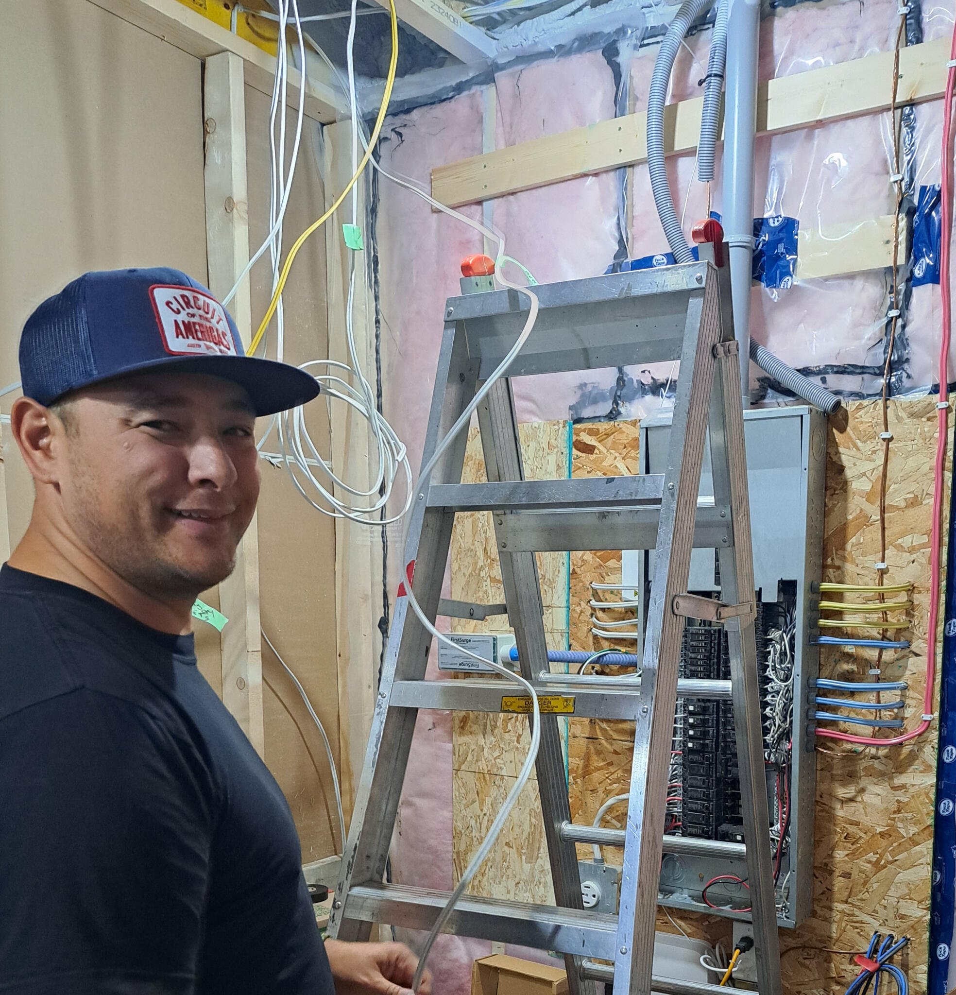
I assume the SPD in your photo is a Siemens First Surge Type 2 surge protector, (SPD).
From your photo the length of the PVC nipple looks like it is about 2ft. ??? Camera lens can be deceiving though.
I only pointed out what the manufacturer of the SPD states in their installation instructions. From what I read on the Net the First Surge type 2 SPD comes with 36" leads.???. Is that correct? That’s nuts when in the installation instructions it says to keep the leads as sort as possible. (Well, that’s what you did for your installation). Siemens engineer’s know the length of the leads matter...
I installed an Eaton CHSPT2ULTRA Type 2 SPD at my main electrical service panel, a few years ago. LOL, the main gripe from home owners that installed the Eaton SPD themselves was the leads were too short... It comes with 18" leads. (I didn’t have any problem. In fact I cut them of even shorter.) Unlike Siemens Eaton does not install extra long leads and tell the user to cut them off making them as short as possible. What a waste of wire. (FWIW, Eaton as well as Siemens warranty says the SPD must be installed by a Licensed Electrician.)
.
If an extra 6 inches of wire makes a difference, when electricity is travelling at 300,000 meters per second,
In the event of a high voltage transient surge, a transient surge lasts less than a blink of an eye. Measured in microseconds to milliseconds... An SPD has to react fast. A good type 2 SPD will respond in a nano second or less. That’s Fast!
Actual distance of SPD from panel bus test measurements.
Looking at your photo again... Again the camera lens can be deceiving... It looks like there is room to mount the SPD against the side of the panel. Can you post a better picture of the panel area?
W I R E L E N G T H E F F E C T O N C L A M P I N G VOLTAGE
Since surges are fast transient events, the response
of the circuit is different than that of the nominal AC
voltage at 50 or 60Hz. The rapid change in voltage
appears to the circuit as a high frequency signal
and at higher frequencies AC circuits have more
impedance. The equivalent frequency of the UL
combination wave voltage is 208.3kHz. The main
cause of this frequency response is the inductance
of the circuit. Simply adding more wire to a circuit
adds more inductance and thus higher impedance
to the high frequency surge event. Longer lead
lengths of SPDs will increase the clamping voltage
and reduce their performance in protecting downstream loads.
Just for the heck of it I pulled the panel cover off and checked the length of the wires from the SPD to the 2 pole 50 amp disconnect breaker for the SPD. About 6 inches. Yours? It doesn’t matter whether your SPD can react in a nano second or not. (Though the surge event doesn’t last much longer than that). Question is how high will the voltage rise before the voltage is clamped? I guess I haven’t done a good enough job of getting that across to you. My bad...
If it wouldn’t be a problem would you email this thread to your Son-in Law and get his opinion? You said he is a Master Electrician. That tells me he doesn’t wire houses for a living. He’s involved in the wiring of Commercial and Industrial facilities. Good chance he runs jobs...
I had already ran two dedicated 20A lines into my living room. A 10AWG stranded line for all the audio crap and 12AWG Romex (solid core) line for the TV and computer crap including the Streamer.
.
I’d installed a junction box inside the garage and fed the two 20 A lines into it and then via flexible Armored Cable, ran H,N,GND wires inside the one conduit
I’m not a fan of stranded wire for feeding audio equipment. I would of used solid #10 wire.
How are the H,N,Grd pulled in the conduit? Just loosely, randomly? Best practices, (for feeding Audio/Video equipment), is to twist the Hot and Neutral conductors together the entire length of the conduit. Pull, install, the insulated EGC (Equipment Grounding Conductor) straight along side the twisted pair in the conduit. Good chance you would have a lower noise floor than you have now.
AC current flowing through a conductor will create an AC magnetic field along the entire length of
the wire, the magnitude of which will vary in proportion to the amount of current. This field may
inductively couple noise voltage to signal wires running parallel, which can result in hum and buzz.
The longer the run of these parallel wires, the greater the inductively coupled noise voltage will be
Also the loosely, randomly, installed H & N current carrying conductors will induce a voltage/noise onto the EGC.
Note the chart on page 35. The worst case is H, N & EGC conductors pulled loosely, randomly, in a conduit. Best is the H & N twisted together with the EGC pulled straight along side the twisted pair.
You must have a verified phone number and physical address in order to post in the Audiogon Forums. Please return to Audiogon.com and complete this step. If you have any questions please contact Support.