I've been repairing/restoring/rehabilitating a great 30-year old pair of speakers and I have some questions stemming from my novice inexperience.
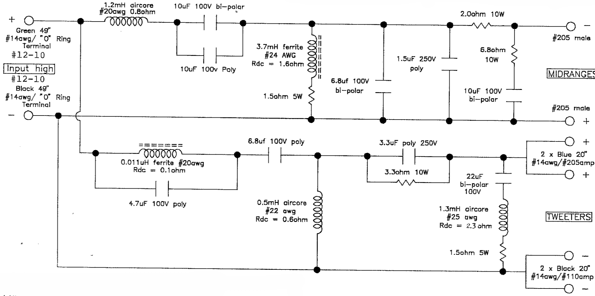
1) In the woofer part of the crossover, the schematic shows a "100uF 100V bi-polar" in parallel with the woofer. My existing crossover, spare crossover that I purchases, and in every photo that I've seen of the crossover, they use two 47uF caps instead of one 100uF cap. Why?
Why not two 50uF caps (which certainly appear to be available)? I understand that two smaller value caps might perform better than one large value cap (correct me if that understanding is wrong), but why use 47uF caps?
I will certainly re-build this cross over with some type of Metalized Polypropylene cap. But do I use two 47uF (maybe with an added higher-quality bypass cap) or two 50uF caps?
2) In the midrange section of the crossover, it has two 10uF caps in parallel wire in series with the midrange drivers. See attached snippet from the schematic:
As with the woofer circuit, I will probably replace these with Metalized Polypropylene caps. I assume I can use one 20uF poly cap rather than two 10uf poly caps without any significant difference in quality. Or will two 10uF actually be much better?
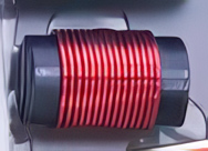
3) In the tweeter circuit there are 3 inductors. The first in series with the tweeters is a very small 0.011uH ferrite core inductor with a Rdc of 0.1 ohm (the other 2 are 0.5mH and 1.3mH inductors wired in parallel with the tweeters). See: 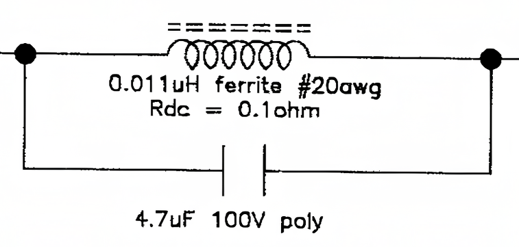
None of the speaker parts sellers (Madisound, Parts-express, Parts-connexion) have any inductor that small. Is that possibly a typo? (I will have to see if I can measure the inductor) 0.011uH = 0.000011mH = 11nH. Does a value that small make any sense to any of you? I would like to replace it with an air core (for obvious reasons) and I can find air core inductors in roughly that size (0.010 uH) on digikey.com. But the size does seem strange to me. Further, if it is correct, the Rdc of the inductor will almost certainly be different. Do I need to compensate for the different resistance in the circuit, and if so how or where would I do that? Thanks!